Field Irrigation Sprinklers: Test Spacing Before Buying a Full Block
Run a representative catch-grid trial at the intended pressure, then set spacing from the measured pattern, wind, soil intake and available flow.
Published by IrriNex Store
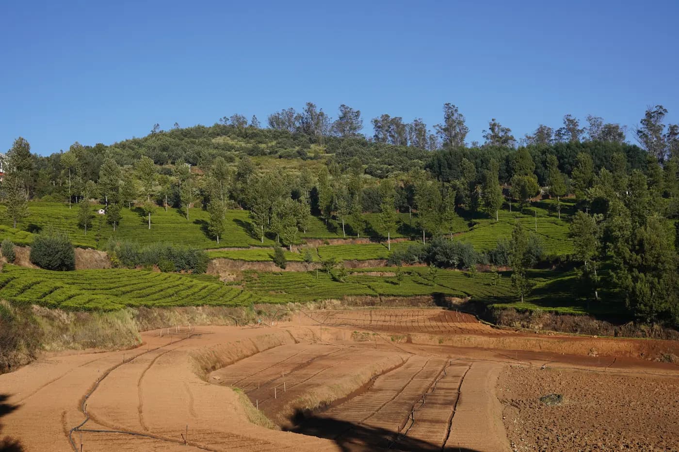
Field irrigation sprinklers should be spaced from a measured pattern, not from a radius copied off a product page. Before buying a full block, set one candidate head at the intended operating pressure, place a catch grid across a representative area, and observe how neighboring spray patterns contribute between positions. The trial helps answer a practical question: where can another head sit so that the ground between heads receives a useful combined pattern under the conditions in which the block will actually run?
A catalogue radius describes a model under stated conditions; it does not prescribe universal row spacing. Wind, pressure at the head, nozzle condition, soil intake and total flow all change the buying decision. This guide turns a limited field trial into a documented layout and quote request. It is about selecting spacing by overlap before purchasing quantities, not measuring seasonal application depth as in the field catch-test guide or calculating simultaneous head count as in the sprinkler zone flow calculator.
Choose a test area that represents the future block
First sketch the block that you may equip. Mark crop rows, row direction, head positions under consideration, field edges, slope, trees, fences, buildings, access tracks and the point where water enters. Indicate the normal wind direction and note whether the block is sheltered or exposed. A trial in an open corner cannot automatically describe a sheltered interior, and a test beside a hedgerow cannot show the pattern in the middle of an unobstructed field.
Pick a representative patch where the planned head will stand safely and where containers can be placed without trampling crop or creating a trip hazard. Mark a trial center and the candidate directions for the neighboring heads. If the intended layout is rectangular, test the likely along-row and between-row directions. If the field boundary is irregular, test an interior pattern and a separate edge condition. Keep those results distinct: edge overlap differs because a boundary head has fewer neighboring contributions.
Use one identified head, nozzle and support arrangement for the trial. Record the model and nozzle markings, riser height, arc setting if adjustable, and whether the head rotates freely. Clear debris only according to the equipment instructions; do not alter a nozzle, spring or deflector just to make a test appear better. A changed component creates a different test configuration. Note the date, time, crop stage, recent rain, soil surface condition and approximate wind. These details help you decide whether the result represents the planned irrigation window.
A one-head trial is a useful screening step, but it cannot prove a whole block will perform uniformly. Its purpose is to map the pattern and identify promising spacing candidates for a small overlap trial. If the block has strongly different soils, slopes, shelter or water supply routes, divide it into representative zones and treat each as a separate layout decision.
Stabilize pressure and record conditions before collecting water
Operate the candidate head at the pressure expected in service, measured while water is flowing. Static pressure with the valve closed is not the working condition. Use a suitable gauge at or near the operating riser, and record the gauge location, reading and whether other outlets were open. A pressure value observed at the pump does not necessarily equal pressure at a distant head after pipe and fitting losses.
Allow the system to settle before the timed collection begins. Watch for a changing gauge reading, pulsing supply, partial rotation, leakage at a joint or a neighboring user switching on. If pressure changes during the run, stop and correct the cause or record the run as unstable. Comparing catches from an unstable trial with a steady trial can confuse a supply problem with a spacing problem.
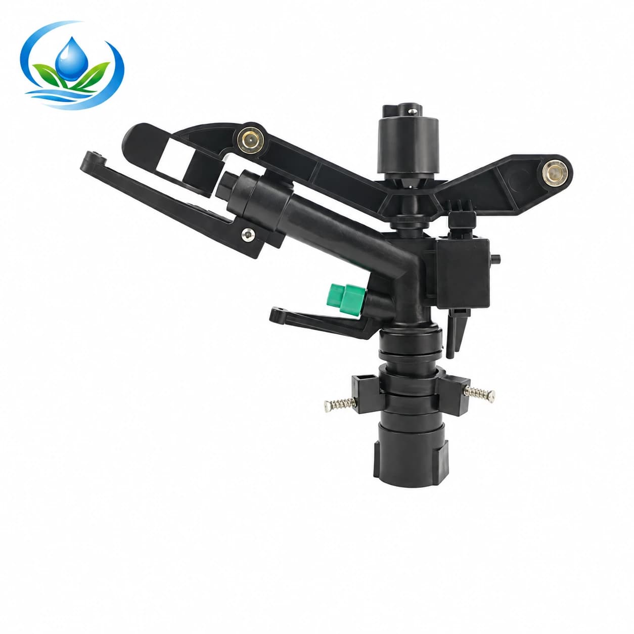
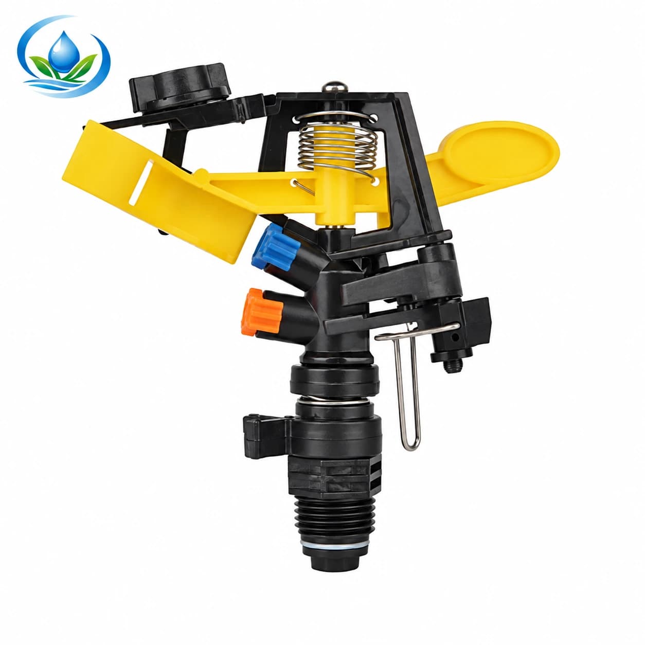
Write down the intended operating pressure and the actual reading, then compare them with the exact head option being evaluated. For reference, the published S50 listing gives a working range of 2.0–5.0 bar and the 9703K listing gives 1.5–3.0 bar. Their ranges do not identify an ideal pressure for your particular block, and one model's figures must not be assigned to the other. Confirm the exact option and nozzle before applying catalogue figures to a quote.
Wind is part of the test condition. Record direction and whether the spray visibly drifts, and postpone the measurement if gusts make the pattern unrepresentative or unsafe. A calm-weather pattern may be valuable for comparing candidate heads, yet exposed fields may need a second trial during a more typical operating window. Do not compensate for drift by assuming every head should simply be moved closer; closer spacing increases head quantity and total flow, while strong wind may require a different operating plan.
Build a catch grid for a useful pattern map
Use identical, stable, straight-sided containers with openings wide enough to collect spray consistently. Put them on a regular grid around the trial head, including near, middle and outer portions of the wetting pattern. Extend the grid beyond the apparent wet edge so that a dry perimeter is visible rather than omitted. Mark every container position on a sketch and measure the grid intervals. The grid spacing is a sampling choice for this trial, not the eventual sprinkler spacing.
For overlap, place a second line or grid across a likely neighboring position. The most useful points are often between candidate head locations, where the two patterns should combine. A single head's outermost visible droplets do not tell you how much water is delivered at that point. Catches at the centerline between proposed positions show whether the neighboring contribution fills a thin band, remains weak, or creates an unexpectedly heavy patch.
Keep the containers level and the openings clear. Avoid placing them in wheel ruts, under foliage, beside a post that blocks spray, or where splash from a hard surface can enter. If crop canopy will intercept water, consider whether the trial should be above or within that canopy to represent the intended measurement question. Use the same container type and placement method for each candidate spacing so comparisons are fair.
Run the sprinkler for a set period long enough to collect readable water without overflowing the containers. The appropriate duration depends on the pattern and container size; start with a short safe run and adjust if catches are too small to read. Use a ruler or graduated cylinder, label each reading by grid point and note the run time. The aim here is pattern comparison and overlap diagnosis. If you need application depth per hour or distribution uniformity for a whole operating zone, run a separate, properly designed test; see the guide to measuring application in an existing block.
Take a photograph of the grid and field sketch, then transcribe the readings immediately. Mark empty, spilled or disturbed containers instead of silently treating them as zero. If one container is obviously contaminated or knocked over, repeat that portion of the trial. A clean record makes it possible to compare a later nozzle, pressure or spacing without relying on memory.
For an example of a square catch-can grid between operating sprinklers and an explanation of low-quarter distribution uniformity, see UF/IFAS guidance on field evaluation of sprinkler application uniformity. Its nursery example is not a target score or spacing prescription for your crop block.
Read the pattern as overlap, not as a radius promise
Lay the measured grid over the proposed layout. Identify low-catch bands that fall between candidate head positions and ask whether the neighboring pattern contributes there. A continuous low band across the middle suggests that the selected spacing or pattern shape may leave a gap under the tested condition. A narrow dip that aligns with a blocked direction may instead indicate an obstacle or a directional pattern limitation. Either finding calls for another controlled trial before you order a field quantity.
Look for the shape of the catch pattern as well as its outer extent. Some heads distribute more water near the head and less at the edge; a second head can improve the middle only if its pattern reaches that location with meaningful volume. Two visible spray envelopes touching in the air do not prove adequate ground coverage. Compare actual collected water at shared locations instead of treating a nominal radius as a circle of equal application.
Test at least two plausible spacings in a small temporary arrangement if practical. Mark candidate positions, run one arrangement, collect the grid, then move the neighboring position and repeat under similar pressure and wind. Keep the test duration and collection geometry consistent. A spacing that looks promising in one calm run remains provisional until it makes sense for normal operation, crop rows, boundary geometry and water capacity.
For a worked illustration, imagine the grid repeatedly shows a narrow weak strip midway between two proposed rows, while points nearer each head collect more. That evidence supports testing a closer between-row distance or a different head pattern. It does not supply a universal distance: the actual adjustment depends on the measured width and strength of the weak strip, the head's tested pressure and the neighboring contribution. Conversely, if the middle points collect consistently while the edge points are low, the problem may be boundary layout rather than an interior spacing issue.
Do not chase identical readings at every point without considering what the crop and soil need. The objective is a defensible design for the intended block, not a perfect laboratory pattern from one head. Compare the low areas with the crop rows, soil variation and practical run schedule. Have a qualified irrigation designer review unusually valuable crops, steep slopes or complex layouts where a simple trial does not resolve the risk.
Check wind, soil intake and crop layout before fixing distances
Wind can elongate or shift the wetted pattern. Compare the catch map with the recorded wind direction: a low strip consistently downwind may reflect drift rather than insufficient nominal reach. Repeat on another representative day if wind direction changes over the irrigation season. If the field normally runs at night or during a scheduled low-wind period, test in that window where safe and lawful, then use that operating condition in the layout plan.
Observe what happens at the soil surface during and after the run. Record where ponding begins, how long it persists and whether water moves downslope. A catch grid can show where water landed, but it does not measure infiltration capacity or determine an irrigation duration by itself. If water ponds while a nearby area remains dry, investigate both delivery pattern and soil intake before buying additional high-flow heads. The ponding diagnostic guide helps separate surface intake symptoms from a head replacement decision.
Relate candidate positions to crop rows, machinery clearance, cultivation paths and harvest access. A theoretical layout may be awkward if risers stand where equipment turns, workers need to pass, or the wettest overlap falls outside the root area. Draw the actual positions and measure distances from fixed field markers. Check that valves, hose routes and head stands can be reached for inspection without damaging plants.
Pay attention to slope and elevation changes. A head at a lower point may experience different pressure from one higher on the same lateral. Run the pattern trial at representative locations, especially the hydraulically farthest or highest candidate position. If readings change substantially from one position to another, the layout decision is not only spacing; pressure regulation, pipe sizing, zone division or a supply issue may need investigation.
Keep a boundary plan. At field edges, corners and obstacles, decide whether to use a different arc, move a position inward, accept a narrower wetted margin or operate an edge row separately. Do not count the boundary head as if it had the same neighbors as an interior head. Keep edge test readings separate from the interior grid so their different geometry remains clear.
Reconcile a promising spacing with total flow
Only after the overlap trial identifies a candidate layout should you estimate the head count. Draw the positions and count interior and edge heads separately. Then add the verified flow requirement for the exact model and nozzle at the selected operating pressure. The total demand is the sum of heads that will operate at the same time, plus any other users on the supply. The running-flow guide explains the arithmetic and why a source reading and pressure check still matter.
For context, the S50 listing shows 3.7–5.0 m³/h and 15–17 m spraying radius across its listed working range; the 9703K listing shows 1.1–1.3 m³/h and 6–7 m radius. These are separate option-specific published figures, not a promise that the entire range applies at every pressure or that the radii define spacing. Do not combine them into a fictional shared model or infer a nozzle configuration not shown for the exact item.
Compare total planned flow with a dependable source measurement while the required pressure is maintained at the most demanding head. If the proposed interior spacing uses more simultaneous flow than the source can reliably supply, consider smaller operating blocks, a different verified option, or revised layout after testing. A lower flow per head can allow a different head count, but it does not automatically produce the needed overlap or pressure. Keep pattern suitability and hydraulic capacity as separate gates.
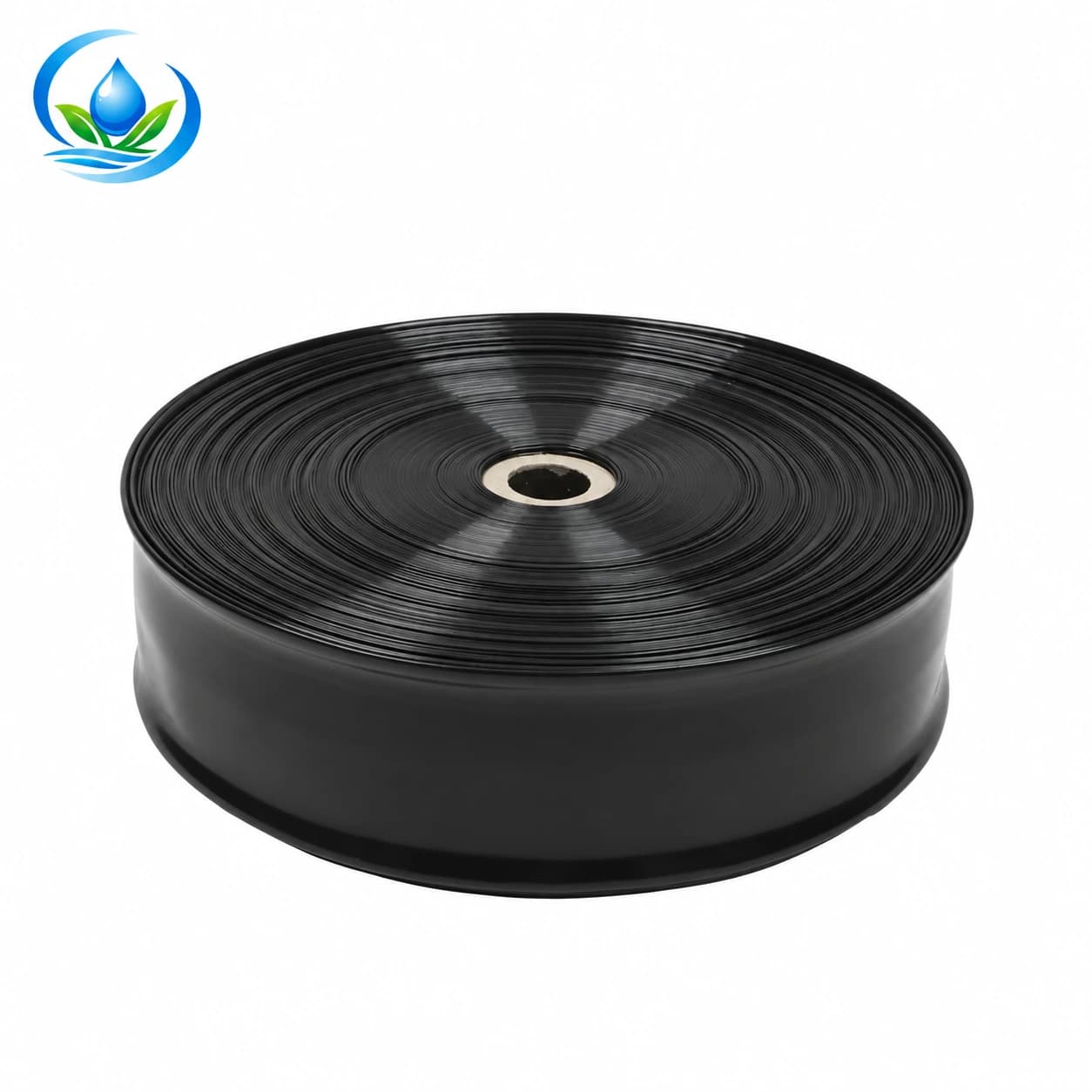
Consider the supply route and its fittings as part of the request. The listed PE layflat hose record includes selectable diameters, working-pressure entries, burst-pressure entries and roll lengths; do not treat the family list as one assembled product specification. Identify the exact diameter and pressure option, length, end connection and any couplers required. Check losses along the route and whether the hose can be laid without kinks, vehicle damage or unsafe crossings.
Compare candidate heads from their own verified records
The S50 and 9703K should be considered as separate candidates against the field evidence. S50's listed radius is broader and its listed flow is higher than the 9703K figures, while its working pressure range also differs. That makes neither model automatically superior. If the block has a large spacing candidate, test the exact head and operating condition that could support it; if flow is limited, do not assume a smaller listed radius can cover the same area without more positions.
Match the test head to the exact listing and installation connection. S50 is listed with a 1-inch female inlet; confirm the mating riser and thread standard rather than assuming nominal size establishes compatibility. The 9703K listing specifies a 4.0 × 1.8 mm nozzle and does not inherit S50's inlet fact. Ask for any connection detail absent from the exact option page before ordering or adapting existing pipework.
Both sprinkler listings are published, but online ordering is not currently available; request current price and availability. A published page is not proof of stock. Send the supplier the field sketch, catch readings, operating pressure, source flow, crop-row direction, proposed quantity and exact model under consideration. Ask for a quote that identifies the SKU, nozzle, inlet, pressure and flow basis, included fittings, quantity, lead time and current availability.
If you are comparing a third-party head already installed, record its markings and connection separately. Do not choose a replacement by visual resemblance alone. The impact-head replacement guide covers model and connection checks; this article's added decision is where to place the heads after a measured overlap trial.
Turn the trial into a practical quote and installation plan
Prepare a one-page request with a scaled field sketch, dimensions, crop rows, elevation notes, candidate positions and boundary treatment. Attach the grid map and container readings, test duration, pressure location and reading, nozzle and head identification, wind direction, soil observations and a photo. State whether the trial ran with one head or a temporary neighboring arrangement, and label every observation as measured, estimated or still unknown.
Ask for a comparison that preserves the distinction between candidate products. For each option, request the exact inlet and thread, nozzle, working pressure, flow at the proposed operating point, stated pattern/radius basis, compatible stand or riser, and any recommended filtration or service requirement supported for that item. Ask the supplier to identify which values are documented and which need confirmation. Avoid a quote that simply states a nominal radius and a quantity without explaining the operating condition.
Include the hose and connection details in the same request if the system needs a new supply route. Specify the route length, whether the hose is stationary or moved, maximum measured working pressure, expected flow, connection sizes and crossing points. Online ordering is not currently available for the PE layflat hose; request current price and availability for the exact diameter, pressure option and roll length instead of assuming a selectable combination is in stock.
Before committing to the full block, arrange a small pilot section with the intended spacing and simultaneous operating group. Check pressure at the farthest head, observe rotation and obstruction, repeat catches between heads, inspect the soil surface and confirm the source remains stable when other planned users operate. The pilot validates the combined layout more directly than extrapolating a single-head radius. Record any changes and update the final head count only after the test.
Use a simple decision rule: retain a candidate spacing when the representative overlap grid has no persistent weak band important to the crop, the pressure and flow remain within the exact option's documented operating basis, the soil accepts the applied water at the intended run, and wind conditions are representative or managed. If one gate fails, fix that cause or trial another arrangement rather than ordering more of the same head by guesswork.
Buying checklist: what to confirm before the full-block order
- Field dimensions, crop-row direction, slope, obstructions, edges and practical equipment access.
- Catch-grid sketch with container spacing, timed readings, candidate head positions and points between heads.
- Exact test head and nozzle, running pressure and gauge location, operating group and observed wind.
- Soil intake and ponding observations, including where and when pooling first appears.
- Exact option-specific pressure and flow data, inlet connection and unresolved compatibility questions.
- Simultaneous head count, other water users and measured source capacity while pressure is maintained.
- For PE layflat: exact diameter, pressure option, roll length, route, end connections and couplers.
- Quote identifying SKU, quantity, included parts, current price and availability, lead time and delivery basis.
- A pilot arrangement and repeat check before converting the trial into a full-field quantity.
Spacing is the result of how patterns combine at the crop under a documented operating condition. Test that overlap, then test the implications for pressure, wind, soil intake and total flow. A radius can help screen candidates; only a representative field trial can show whether the proposed spacing suits your block.
For a broader wind comparison, read the field guide to wind exposure and sprinkler-head selection; it focuses on the exposure decision, while this trial maps a proposed layout. The head replacement checklist is useful when the trial points to a different model or connection. For products, review the separate S50 listing, 9703K listing and PE layflat hose listing. Each record describes a distinct option, and online ordering is not currently available; request current price and availability.
Before you order
Compare this guide with the specifications for your exact product, selected option, water supply and field conditions. Your equipment requirements take priority over a general example.
Compare irrigation products