
Irrigation Valve Buying Guide: Manual Shut-Off Connections and Quantity
Compare manual compression, BSP union, barbed and locking tape valves, then count control points and prepare installation checks.
Published by IrriNex Store

An irrigation valve should match the connection and the part of the crop block you need to isolate. For a manual shut-off, compare compression ends for PE pipe, BSP threaded unions, double-barbed tubing connections and locking tape connections before comparing handle shapes. This guide turns an existing irrigation layout into valve specifications, quantities, matching accessories and installation checks. It distinguishes general connection types from the currently linked IrriNex Store options; confirm the selected variant, supply and price before ordering.
Describe the isolation job in one sentence
Write down what should stop when you close the valve: one crop row, a group of laterals, a tunnel supply or a serviceable section of pipe. Then identify which outlets should continue working. This simple description prevents buying a convenient-looking valve that controls the wrong portion of the system. Walk the route and mark the actual junctions rather than assuming every visible pipe leads to the nearest bed.
A hand-operated valve needs someone to reach and operate it. If your requirement is timed watering, remote control, automatic pressure regulation or overpressure relief, identify that requirement separately. A manual handle does not provide those functions. In a system with automatic watering, manual isolation can still be useful for maintenance, provided the arrangement follows the equipment instructions.
Record both ends of a manual irrigation valve before ordering
For each proposed valve, record inlet material, inlet dimension, outlet material and outlet dimension. Add thread standard where relevant and photograph both ends. An apparently simple inline replacement can involve different connections on each side. A mixed assembly may need an adapter; include it before comparing the cost and installation length of competing options. A manual irrigation valve connection comparison should name the upstream and downstream interface separately, especially when one side needs an adapter.
Use the dimension specified by each fitting family. Compression fittings are chosen against pipe outside diameter. A barbed fitting must match the tube it enters, including the effect of its wall on the internal passage. Tape fittings need the appropriate tape diameter and wall range. Nominal thread size belongs to a thread system, so do not equate a half-inch thread with a 16 mm tubing connection.
Choose compression for a matching PE pipe route
A compression ball valve can isolate a PE pipe route when both pipe ends match its specified connections. No matching compression ball valve is currently listed in this store, so this section describes the connection type for planning. Obtain the exact size, pressure class and installation instructions before sourcing one. A valve’s rating is not a recommendation to run downstream drip tape at that pressure.
Measure a clean, undamaged pipe section and inspect its roundness. Confirm insertion depth, any required support insert and the assembly sequence before cutting the installed line. Leave enough straight pipe to seat both ends without using the valve to pull them together. Support the adjoining pipe so movement, weight or seasonal handling does not twist the body.
Use a union where the installation needs separation
A single-union ball valve provides a service separation point in a compatible threaded route. No matching single-union model is currently listed in this store. For this connection type, confirm the actual thread size, standard, pressure rating and sealing method before ordering from a supplier. A broad BSP label alone does not establish that two selected parts will connect or seal correctly.
Allow room to loosen the union and withdraw the part after shutting down and relieving pressure. A union does not make it safe to disconnect a live line. Check the mating faces and seal, and confirm whether the connection needs a gasket, approved thread sealant or another prescribed method. Do not transfer a sealing practice from a different valve merely because both have threads.
Match a double barb to round tubing
The double-barbed shut-off valve for 16/20 mm tubing can create a manual isolation point between two matching tube ends. The documented variants include V16A for 16 mm and V20A for 20 mm. Inspect the tube on both sides: an end stretched around an old fitting may need cutting back to sound material before fitting the replacement.
Check the selected model's pressure limit and any clamp requirement rather than assuming every small valve uses the same installation method. Push the connection straight and preserve enough slack for normal movement without pulling against the barbs. A valve intended for round tubing should not be substituted for a locking tape valve on thin tape just because the labels share a number.
Keep locking tape connections within their own family
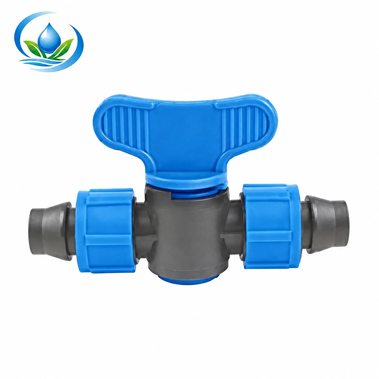
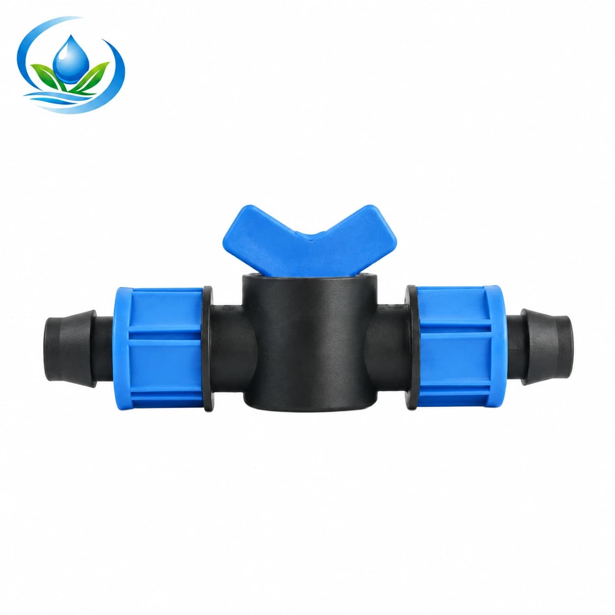
The 16 mm locking tape coupler valve combines a tape join with downstream isolation; its model is V161 at 16 × 16 mm. The separately listed 20 mm tape coupler valve is model V20IL. Choose the exact tape model and confirm its wall compatibility. The V16 and V20 lock-pipe coupler models belong to a different connection family.
Lay the tape straight on each side, use sound ends and follow the locking sequence. Avoid folds at the nut or a bend that loads the joint. This inline coupler is a different connection task from punching a take-off into a header. If your actual job starts a new row at the supply, map that take-off assembly separately before ordering.
Compare function and fit together
| Valve family | Connection to verify | Useful purchase question |
|---|---|---|
| Compression ball valve | PE outside diameter and model pressure class | Can both pipe ends seat without strain? |
| Single-union PP valve | BSP thread details and union seal | Can the union be opened and the part removed? |
| Double-barbed valve | Round tubing size, wall and retention | Are both tube ends sound and compatible? |
| Locking tape coupler valve | Tape diameter, wall range and locking model | Does the task require an inline tape join? |
Use the table to eliminate mismatches, then compare the complete installed assembly. None of these connections is universal. A photograph can identify a connection style, but it cannot establish the operating limit, exact variant, supplied accessories or package quantity.
Check flow and pressure at the proposed location
List the outlets that can operate simultaneously downstream of the valve. Use their specified flow at the intended operating conditions and include the effect of shared upstream equipment. The flow-rate calculation guide helps organize that demand. If a flow-loss curve is needed for a marginal supply, obtain data for the actual valve model; a large connection label alone does not establish low loss.
Compare upstream operating conditions with the limits of the valve, adapters, pipe and downstream equipment. Read the drip pressure checklist when the available pressure is uncertain. Partly closing a manual valve is not automatic pressure regulation, and its position is not a calibrated flow setting. Do not conceal a pressure problem by repeatedly changing handle position.
Count shut-off valves from the routes each one controls
As a purchasing example, consider a mapped installation with three PE supply branches, eight independent round-tube rows and four tape extensions that need separate isolation. If those are fifteen distinct control points, the working list is three appropriately sized compression valves, eight matching barbed valves and four matching tape coupler valves. The calculation is a quantity example, not approval of the hydraulic layout.
A union valve may replace a planned assembly at one service point; do not automatically add it to every row. Check whether a row already has a suitable start valve before buying a second control for the same purpose. The zone planning guide addresses which rows should operate together; this valve list records the connections needed after that decision.
Add the parts that make each valve installable
- Exact valve model, size, quantity and controlled route.
- Compatible adapters for any change in material, dimension or thread.
- Specified seals, retention parts, clamps or support inserts.
- Enough replacement pipe or tape to remove damaged ends.
- A suitable square-cutting tool and appropriate measuring tools.
- Support and identification labels that remain readable in the field.
- Separately counted spares for the valve families actually installed.
Check what is included with each selected option. An accessory shown in an installation photograph may be supplied separately. Confirm whether the listed quantity means individual pieces or packs, and calculate the number of packs from the required piece count. Keep your spare allowance visible so a later reviewer can distinguish installed equipment from reserve stock.
Keep water treatment and protection in the plan
University of Minnesota Extension's specialty-crop irrigation guidance treats filtration, pressure regulation and backflow prevention as separate equipment decisions. A manual isolation valve does not replace those functions.
When the valve sits near fertilizer injection equipment, confirm the wetted-material and seal compatibility with the actual solution and follow that equipment's instructions. Do not assume a valve that isolates ordinary irrigation water is approved for every concentrate. Plan a controlled way to depressurize and inspect the isolated section. The product name does not establish chemical suitability or approval as a backflow device.
Place handles where the crop will not hide them
Check access with the mature crop, covers and working routes in mind. Leave room for the complete handle movement without contact with another pipe or a bed edge. Avoid locations where a tool, foot or moving hose will routinely strike the valve. If several controls sit together, label them by the actual row or branch rather than by the order in which you installed them.
Also check removal space. A compact valve can still require a long withdrawal distance, especially where pipe is stiff or a union is close to another fitting. Include that space in the dry layout before cutting. Easy access makes it more likely that routine isolation and reopening are performed correctly during a busy harvest period.
Receive the order and assemble one sample
Compare the delivered labels, model numbers and quantities with the purchase list. Inspect threads, barbs, locking nuts, sealing faces and handles for damage. Keep visually similar sizes apart and retain their packaging references. If a part lacks identification, resolve it before forcing it onto a pipe as a way of guessing the size.
Make one sample assembly from each connection family using the actual pipe or tape. Follow the manufacturer's preparation and tightening instructions, then check it under permitted operating conditions. A connection that feels firm while dry still needs a leak and operation check. Resolve a poor fit before repeating the assembly across all fifteen control points in the example.
Use a clear installation acceptance sequence
- Stop the supply and release trapped pressure using the system's prescribed method.
- Verify the route, valve identity and both connection types.
- Prepare clean, square and sound ends without pushing debris into the line.
- Assemble seals and retention parts in the specified order.
- Support the pipe and confirm handle and service access.
- Restore supply gradually and inspect every joint.
- Operate the control and verify that the intended downstream route responds.
- Reopen as required and check the outlets supplied by that route.
Allow residual water to drain before deciding whether continued downstream flow indicates a sealing problem. Record any persistent leakage, unusual handle force or connection movement and stop to investigate. Reinspect after a full operating cycle and after the first layout change. A successful test confirms this installation under its tested conditions, not compatibility with every future arrangement.
Resolve symptoms before buying another valve
A leak at a connection calls for a check of dimension, preparation, seal and assembly. Persistent flow through a closed valve calls for a check of the correct control point, trapped or alternative flow paths, debris and the valve's condition. Difficult handle movement should not be overcome with an extension bar unless the manufacturer explicitly provides for that operation.
If the downstream supply is weak when the valve is open, check the entire route, including filters and adapters. Replacing the valve with a larger connection may introduce more adapters without solving the restriction. Send a photograph, model details and operating observations when asking for help; a symptom such as “low pressure” is much more useful when accompanied by measurements and the active row count.
Finish the purchase list with confirmed details
Before ordering, every line in the list should identify a task, exact valve option, both mating connections, required operating conditions, accessories and quantity. Confirm current supply, price and package contents. Where a rating or compatibility detail remains missing, request the specific information instead of assuming it from another member of the family.
Start your comparison with the currently linked valve options, then use the IrriNex Store contact page to confirm unresolved selection details. Keep the completed list and first installation check together. They provide a practical reference for buying matching replacements, adding another crop row and explaining the controls to the next person who operates the irrigation system.
Before you order
Compare this guide with the specifications for your exact product, selected option, water supply and field conditions. Your equipment requirements take priority over a general example.
Compare irrigation products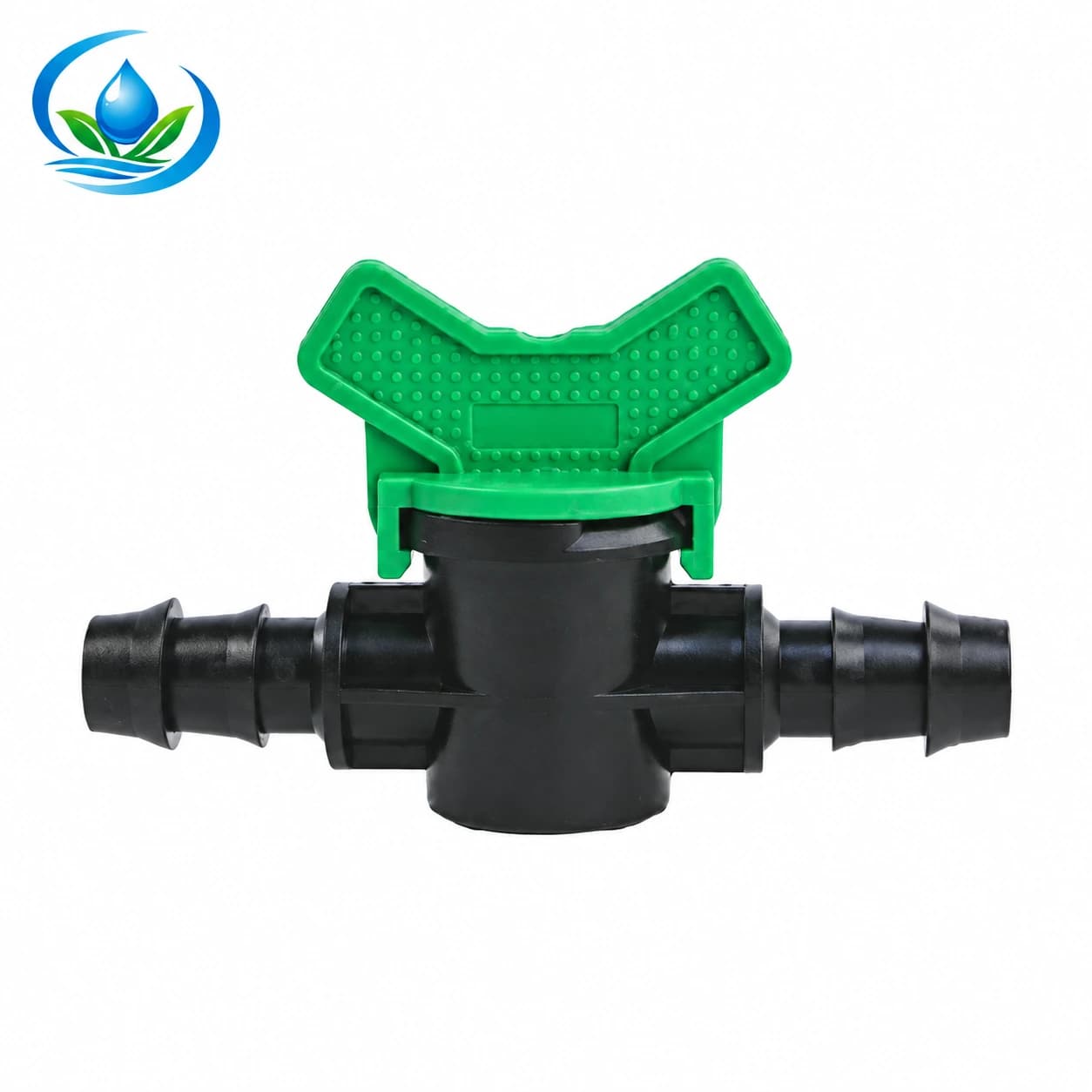
.jpg)