Drip Tape Installation: Which Side Faces Up?
Find the actual emitter side of flat drip tape and keep it correctly oriented through reel payout, first-row laying and end connections.
Published by IrriNex Store
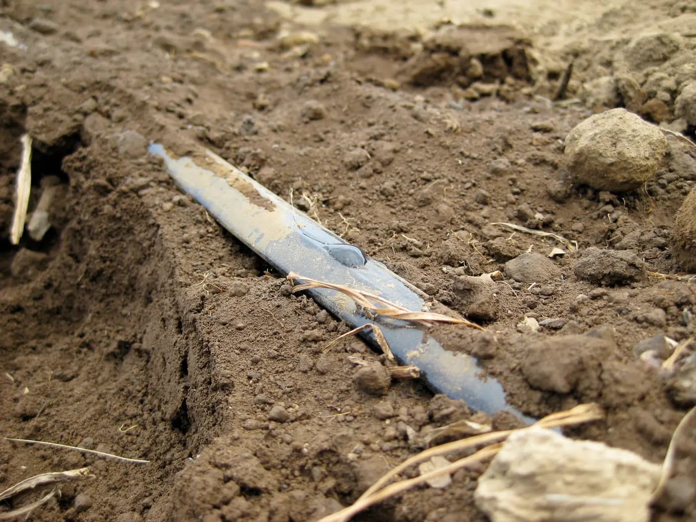
Drip tape with flat built-in emitters is generally installed with its emitter side facing upward, following the exact roll's instructions. The practical difficulty is identifying that side and keeping it there while the reel feeds, the line crosses the bed and the ends are connected. A coloured stripe can help on a product whose manufacturer identifies it as an orientation mark. It is not a universal code. Before opening several rolls, check the actual outlet construction and lay one accessible row without twists. Mark the outlet-facing side on one trial section before laying the first row; verify its orientation at both connections instead of trusting an unverified stripe. Drip tape emitter-side orientation is confirmed on an accessible trial section at both connections before the reel is paid out.
This check is for surface placement of an identified flat tape in agricultural crop rows. It does not qualify an ordinary roll for permanent burial, identify every round dripline's correct position or choose the crop's water requirement. The useful result is a first-row handling method that the crew can repeat, together with the exact tape and confirmed end fittings needed for the remaining rows.
Which side of flat drip tape carries the emitter outlet?
Keep the packaging and selected option record beside a short, clean piece of the supplied tape. Find the repeated factory outlet positions without cutting through or enlarging them. Depending on construction, the emitter location may be seen or felt through the wall, and the outlet may be a small slit rather than an obvious round hole. Compare what you find with the selected manufacturer's drawing. If the outlet cannot be identified confidently, send a close photograph and the roll code to the supplier before laying a block.
Distinguish an outlet from a manufacturing seam, a printed batch mark, a surface scratch and a coloured line. A continuous mark along the tape does not establish where water is meant to leave. Do not create a new hole to make the side easier to recognize or insert an ordinary button dripper into thin tape. The built-in emitter and wall form the delivered product; puncturing it changes that construction rather than clarifying it.
Mark the confirmed orientation on a sample card using the product identity and a photograph. A helpful card shows the complete tape face, a close view of the outlet and the written orientation instruction. Keep different rolls separately identified if more than one maker or emitter design is used. The drip-tape label guide explains how to record wall, diameter, spacing and package length without confusing their units. Add the orientation reference to that existing identity record.
How can the emitter side stay up as the reel pays out?
Particles carried into a lateral can settle toward its lower internal surface. Placing the flat emitter on that lower side can expose its intake region to settled material. Correct orientation reduces that particular exposure; it does not remove particles, restore a damaged passage or replace the filter. Keep the selected line's filtration and flushing requirements in the installation plan even when every visible outlet points the right way.
University of Maryland Extension's drip-irrigation guidance describes surface tape with the emitter side upward. That supports the general orientation check, not a pressure, spacing or duration for a Store roll. The page also discusses other placements and garden arrangements. None of those statements supplies permission to bury a particular product or establishes pressure compensation for every flat tape.
Do not extend the rule to equipment with a different emitter construction merely because it is black irrigation tubing. Some round driplines have outlets on opposing sides and use different installation directions. Identify the material through the crop-row tubing comparison and read that exact product's instructions. The relevant question is the documented position of its emitter, not which side of an empty flattened tube happens to look smoother.
Set the reel so it feeds without adding twists
Plan a clear dispensing route before pulling the first length. Keep the roll supported with equipment suitable for its size and weight, using the maker's handling method. The reel should feed in a controlled way rather than sliding across abrasive ground. Pulling successive loops over the side of a stationary coil can introduce turns into the line. Stop if the tape begins rotating or tangling; dragging harder can turn a handling problem into a stretched end or damaged wall.
Observe the first few metres as they leave the reel and reach their intended position. Confirm which tape face is uppermost and whether that face stays consistent. An apparently straight route can contain a full twist whose two ends both look correctly oriented. Walk the accessible length and look between outlets, rather than checking only the start and finish. Keep loose soil, stones and tools away from the open end and the dispensing path.
For mechanical laying, use the implement and tape manufacturer's setup procedure. Inspect the guides and contact surfaces for obstructions, rough edges or a route that turns the material. This article does not set a machine speed, brake force or pulling tension. Those values depend on the equipment and tape. Have the operator stop the implement safely before inspection or adjustment; nobody should reach into a moving reel or guide to straighten the line.
Lay one row before repeating the method
Choose a first row that represents the actual bed shape, approach to the header and available working space. Check the emitter position along the row while the material remains unpressurized and accessible. Let it follow its permitted route without forcing tight corners or putting it beneath a wheel, tool edge or sharp clod. If a different route is needed at the bed end, identify the appropriate supply connection rather than bending the emitting tape into an unsupported shape.
A local twist should be corrected without turning it into a hard crease. With the supply isolated and pressure released, follow the tape's handling instructions to lift and settle the affected reach. If both ends are already fixed, a permitted disconnection may be needed so the tape can relax. Do not rotate a locked fitting against the wall or pull on a pressurized line. A kink that remains visibly damaged after correct handling needs a separate repair or replacement decision.
Keep this inspection distinct from choosing emitter spacing. Orienting an outlet upward does not make its wetted area reach every plant, and turning the tape upside down is not a supported way to move water sideways. The crop layout and soil wetting check still have to agree with the selected spacing and placement. For beds that will later receive plastic mulch, the pre-cover bed inspection guide explains why connections and the tested route should remain visible until accepted.
Connect the ends without rotating the finished row
Identify the inlet fitting and end closure separately. The start connects the lateral to its supply; the end seals the other end or provides the intended service access. A closure is not a pressure regulator, and its nominal diameter does not establish that its locking profile accepts every wall sold under that size. Confirm the exact mating construction and assembly instructions before tightening anything on the first row.
Make the permitted clean cut at the intended connection location, keeping the factory outlet clear of the fitting as the instructions require. Support the fitting while assembling its locking part so the tape does not wind around it. Check the outlet orientation again immediately beyond the joint and farther down the row. A connection that seals but turns the first several metres onto the wrong face has left the handling task unfinished.
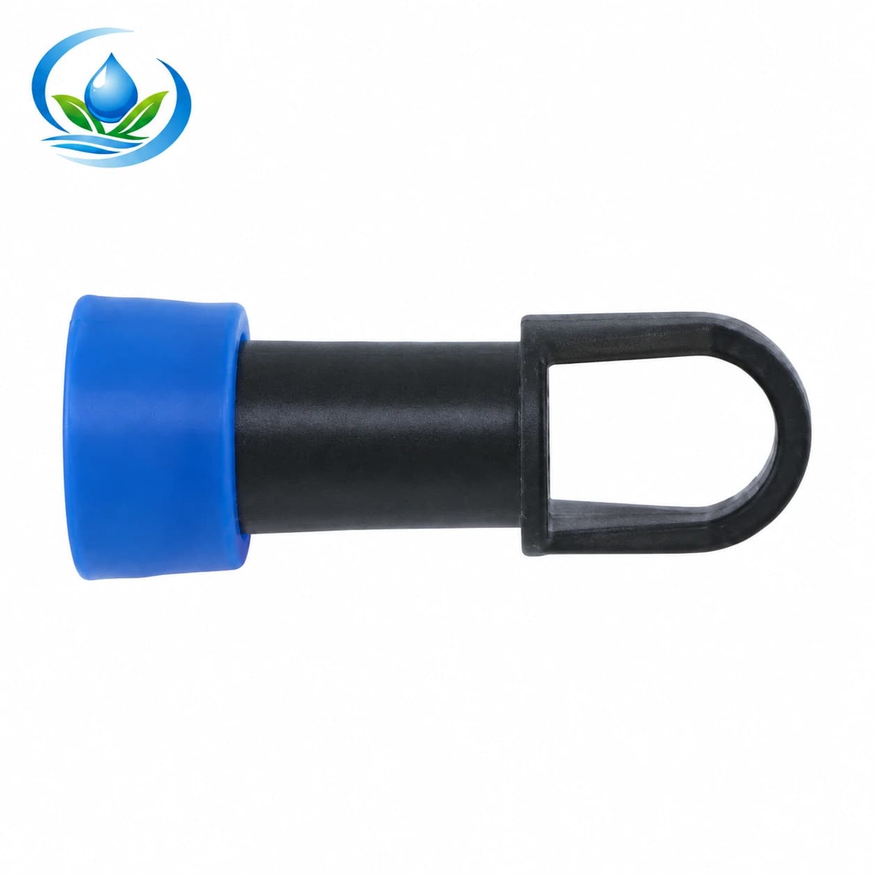
The LE027 lock-ring end cap is listed in the catalogue as a 16 mm closure. That entry establishes an item to check, not a verified pairing with any unidentified 16 mm tape. Ask whether it accepts the selected tape construction and wall, how it is installed and how the end is reopened for permitted service. It is not listed here as an automatic flushing device or a plug for a punctured emitter. The lateral end-access guide helps keep the selected closure reachable.
Use the exact tape option as the order reference
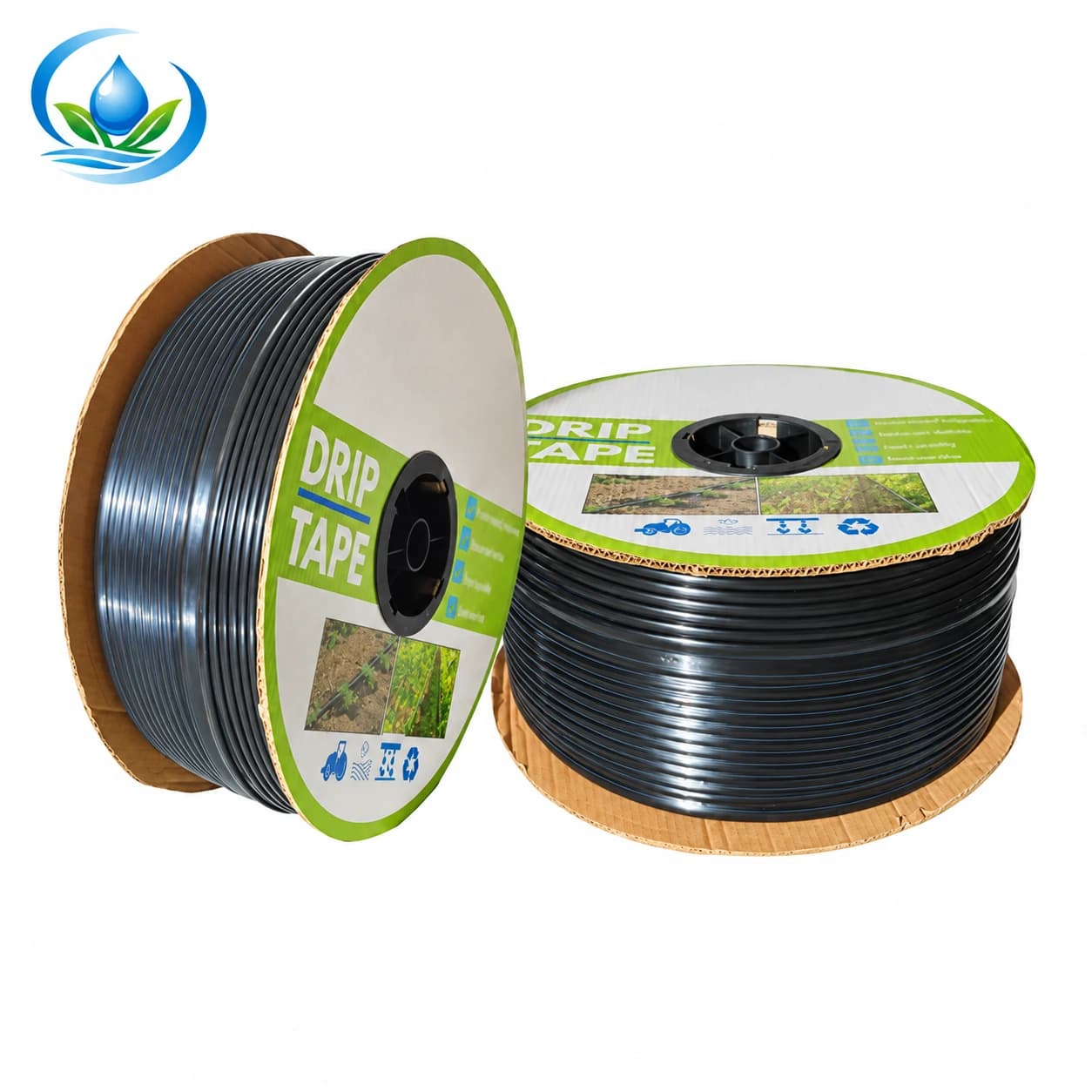
On the flat-emitter drip tape page, option IS-2-C526AC2D85 identifies a 2,000 m sale roll. Its named diameter is 16 mm, its wall is 0.2 mm thick and its outlet interval is 30 cm. Keep that full combination on the first-row record. It does not provide a verified flow value for this exact option, an allowable continuous 2,000 m lateral, or a universal pressure limit.
The option record also does not establish a particular stripe colour or say that a blue mark is the outlet side. Request the orientation and installation directions supplied with the actual roll. A photograph of another maker's tape with coloured printing is only an example of that product. It cannot identify the face of material in a Store shipment. If packaging and the received tape disagree, resolve the discrepancy before cutting the reel into field lengths.
Compare the tape and closure as two documented identities. Match the nominal family, actual receiving geometry, permitted wall range and operating limits; then trial the confirmed assembly. An LE027 label and a 16 mm tape label are not, by themselves, a compatibility certificate. Keep any supplier clarification with the order so the next person does not have to recreate the pairing from memory. Check the current sale unit and available ordering route for each item before buying the field quantity.
Observe orientation again during the first approved run
Follow the installed system's required flushing and startup sequence, using the selected tape's pressure limits. Keep an accessible place to observe the row and the end connection. As the empty tape fills, its shape changes. Watch for a reach that rolls over, a connection that turns, leakage away from the intended outlets or a section that remains kinked. Do not hold a turning line down by hand while it is pressurized; stop and investigate through the approved isolation procedure.
Record where an issue appears rather than calling the entire reel defective. A single rotating inlet, an uneven bed contact point and a twist introduced at the dispenser suggest different corrective work. If water appears outside a factory outlet, locate the escape point before choosing a patch or coupling. The irrigation leak-location guide helps separate a wall defect from a nearby loose connection. Orientation alone does not diagnose every wet patch.
A successful short row verifies that particular handling and connection trial. It does not approve a longer row's hydraulic performance or prove every outlet on the reel is clear. Measure the operating condition and representative delivery for the intended installation before expanding. After the line passes, retain a photograph of its orientation at the inlet and along the bed, plus the product and fitting codes. Recheck after later work crosses or covers the route.
Turn the first-row result into the remaining purchase
Count the remaining identified rows and the material required for their approved routes, including measured connection tails and any justified reserve. Keep damaged lengths separate from usable offcuts. If the first-row method repeatedly twists the tape, resolve the dispensing arrangement before buying more material to absorb the losses. If one fitting causes the line to rotate during assembly, confirm a correct fitting and method instead of assuming that every roll needs replacement.
For a recovered roll, orientation is only one part of acceptance. The used-tape inspection guide covers identity, condition and usable lengths before another crop assignment. A new roll with the wrong side upward may need careful relaying; an old brittle roll with the correct side upward still may be unsuitable. Keep these decisions separate in the order record.
Before checkout, compare the selected tape code, package length, required roll count and confirmed closure with the first-row record. Check current price, pack quantity and delivery; ask Store support for any missing orientation or connection document. Leave the crew a labelled sample or photograph showing the actual emitter side and the accepted dispensing direction. That small handoff makes the remaining installation repeatable without treating colour, a familiar reel or a dry-looking connection as proof.
Before you order
Compare this guide with the specifications for your exact product, selected option, water supply and field conditions. Your equipment requirements take priority over a general example.
Compare irrigation products