Drip Tape Fittings: Match a New Roll to Existing Row Valves
Check the tape-facing end of retained row valves against a new roll's diameter and wall before ordering replacement tape for every crop row.
Published by IrriNex Store
Drip tape fittings become a different buying question when a grower replaces the roll but hopes to keep last season's row-start valves. The old tape may have fitted a locking collar, yet a new roll labelled 16 mm can have a different wall thickness or construction. Before ordering enough tape for every row, identify the tape end of each retained valve and ask whether the selected roll is permitted in its exact retention range. A small approved connection trial can settle an uncertain reuse plan while the rest of the rows remain untouched. Record the valve code and roll wall thickness on one row card; matching 16 mm labels alone do not verify the locking collar's retention range. Drip tape valve connector fit depends on the exact retained valve and the new roll's wall, even when both labels say 16 mm.
The valve is only one point in a larger irrigation line. A retained header connection, a valve body, a tape-facing lock and an outlet seal may be different parts of one assembly. A photograph of the complete row start is more useful than a loose collar alone. This guide concerns new tape meeting an existing row-start assembly. It does not select an entire drip system, repair a pressurized leak or turn a 16 mm nominal label into proof that old fittings fit.
Will the new drip tape lock into the retained row valve?
Walk a representative block while the system is safely off. Give each row a number and sketch the supply header, its takeoff, any short intermediate tube, the valve and the tape extending toward the crop. Note which pieces stay in place and which are due for replacement. Some rows may have a different repair history or a different connector from their neighbours. Record the valve and collar markings where legible and photograph both sides with a scale. Do not assume every visible ring serves the tape end.
Separate the two physical interfaces of the retained assembly. At the upstream side, the valve may connect to a header, flexible tube, layflat hose or another part by its own method. At the downstream side, a locking tape socket may grip thin-wall tape, while a barbed tube connector serves a different material. Identify both ends even if this purchase changes only the tape. The barbed and locking fittings guide explains those interface families; the row-renewal question here is whether the actual old tape-facing end accepts the new selected tape.
Inspect the reusable pieces after approved isolation and pressure release. Look for missing collars, split bodies, worn locking faces, damaged threads, hardened seals, distorted tube ends and dirt trapped where the tape seats. A collar that can still be turned is not necessarily fit for another season of service. Mark suspect parts for exact replacement rather than building the purchase quantity around them. Retain one labelled old tape piece and one labelled valve sample for a compatibility discussion; keep their source row known so a good sample from one area is not mistaken for proof about the whole block.
Check tape wall thickness as well as nominal 16 mm diameter
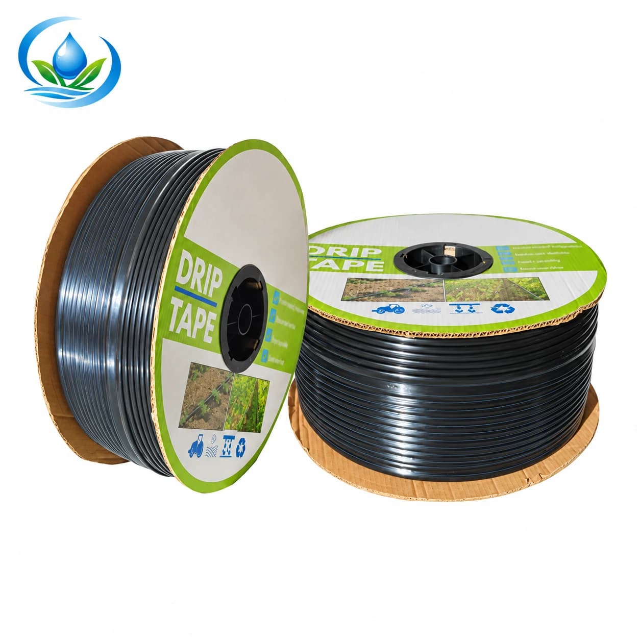
The Store flat-emitter drip tape has separate 16 mm options. One option, IS-2-C526AC2D85, pairs a 0.2 mm wall with 30 cm emitter spacing and a 2,000 m sale roll. Another, IS-2-4F08BF82DC, pairs a 0.15 mm wall with the same 30 cm spacing and a 3,000 m sale roll. Those are different constructions despite the matching nominal diameter and spacing. A longer sale coil is not a permitted single lateral length, and the wall values alone do not show which old locking collar can retain the tape.
Ask for the retained valve maker's allowed tape diameter, wall range, construction and installation method, then compare those with the exact Store tape option. If the old part has no readable code, identify it from purchase records or maker drawings rather than inferring a model from colour. A flattened tape width should not be converted casually into an inflated diameter, and a fitting sold for 5/8-inch tape is not automatically certified for every product called 16 mm. The relevant evidence is the stated mating range for the actual valve and the new roll.
Check whether the old collar and internal tape spigot are a matched pair. A familiar outside shape may hide a different seating profile or a missing retaining piece. If the exact old assembly requires a specified insert or ring, include that part in the sample and the final order; do not combine two brands' rings because they look interchangeable. The maker's instructions should determine how the tape end is prepared, inserted, seated and released. Do not heat, glue, file or add a clamp to make a questionable combination appear tight.
Keep the tape's emitter characteristics on a separate line of the worksheet. Both illustrated Store options specify 30 cm spacing, but confirm the selected emitter flow, operating pressure, required filtration and approved run length for the intended row before replacing the block. Do not infer emitter discharge from wall thickness or from another option on the same product page. Changing the selected roll can change water demand or wetting even when its tape end fits the old valve mechanically. A connection trial and a crop-water check answer different questions.
Do not turn a tape-to-tape valve into a header takeoff
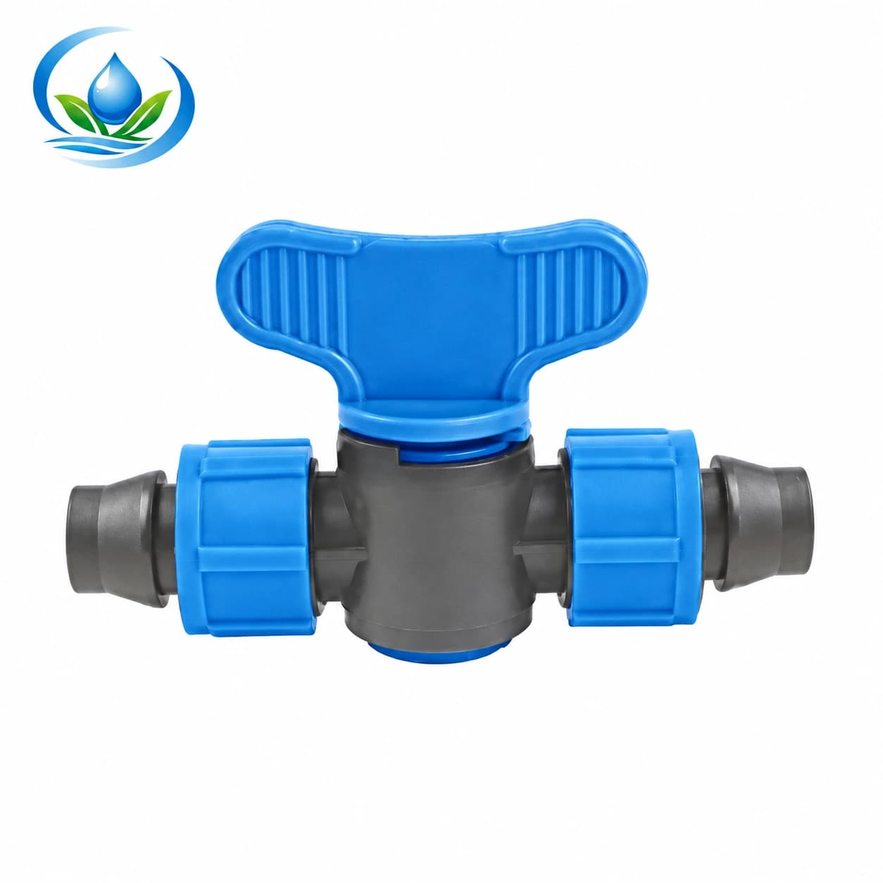
Model V161 places a valve between two tape-facing ends, each nominally 16 mm; its listed designation is 16 × 16 mm. That configuration does not make it an approved offtake from a PE header. If your old row start is a takeoff with one header-facing side, V161 is not an automatic like-for-like replacement merely because it includes a valve and two 16 labels. Draw both sides of the actual connection and select a product with the required upstream interface.
Conversely, a V161 can be relevant where two identified tape ends and a valve are genuinely needed within a row. Confirm the selected tape wall and diameter are permitted on both sides, the offered unit includes the expected locking pieces, and the valve can be operated and inspected at the chosen location. If only one tape side needs renewing, retain a sound old side only when the complete joint remains supported by the component instructions. A new valve cannot make a mismatched tape sound by closing a collar harder.
Do not solve a separate header-thread mismatch by buying a tape coupler. The thread identification guide helps record gender, nominal size, standard and seal when a genuine threaded port is involved. The PE compression guide concerns two PE pipe ends, not thin-wall tape in a lock ring. These distinctions keep the order connected to the physical interface that actually exists rather than an accessory whose picture happens to resemble the old row start.
Test a limited, documented connection before multiplying it
Choose one accessible row whose retained valve and proposed tape option represent the majority of the block. Keep the old valve model or identifying photographs, the new roll code and a piece of original tape with that row record. Obtain the exact valve and tape installation instructions, including whether reuse is allowed and any limits on wall thickness or operating conditions. If the retained valve cannot be identified or the tape-side range is unavailable, pause a broad purchase and ask for the information or choose a documented compatible replacement assembly.
Have the responsible operator isolate and depressurize the section before disconnecting or rebuilding the sample. Inspect the old fitting dry, compare supplied pieces with its instructions and prepare a sound new tape end by the approved method. Do not force a thick or thin tape past a resistance that the instructions do not explain. Do not test fit by pulling on a live joint, increasing system pressure above the allowed range, using compressed air or deliberately leaving an unsupported line to see whether it separates. A quick dry hand fit is not proof of sealing under normal irrigation.
Restart only by the farm's and maker's approved procedure. Observe the sample joint at its ordinary operating condition from a safe position: leakage at the tape seat, movement of the tape relative to the collar, valve function, pressure observations and water emerging from downstream emitters all matter. Check again after a normal shutdown and later approved run if the planned use involves repeated starts. If it leaks or slips, isolate the section before examining the cause. Reconfirm tape construction, damaged parts, seating and permitted retention instead of adding an unapproved clamp or tightening until plastic deforms.
One successful row is useful evidence only for the matching assembly and observed conditions. Group the remaining rows by valve code, collar condition, connection type and supply pressure rather than extrapolating from the best-looking sample. A different header takeoff, older collar or higher-pressure location may need a separate approved comparison. Keep the valve model, tape code, trial date and outcome together. The result should say which exact combination can be repeated and which rows still need a new fitting, further documentation or another test.
Turn the row audit into the right retail cart
Count retained valves that passed inspection separately from valves needing replacement, tape-to-tape joints, upstream takeoffs and spares. Measure the actual row lengths and add the planned replacement amount for each block; use the 2,000 m or 3,000 m figure only as the chosen sale-roll length. If new tape changes emitter flow or row length, revisit how many rows run together and the operating pressure required by that exact option. Do not use a valve count as a substitute for this hydraulic check.
Keep roll labels intact when delivery arrives and allocate the exact codes to the tested rows. The new-roll storage guide covers the period before planting; this fitting check begins at the retained row connection. The crew handover guide helps pass confirmed part codes and unresolved fit questions to the people installing the rows. Do not pre-cut every roll or mix visually similar 0.15 mm and 0.2 mm tape segments before the fit decision is recorded.
For each selected tape or valve option, check the product page's displayed price, selling unit, current availability and delivery details. If a valve's exact wall-acceptance information or ordering option is unclear, ask Store support with both model codes, the old fitting photographs, the new tape construction and the proposed row conditions before buying associated pieces. Buy only the number of replacements supported by that record. A good row-renewal order preserves valves that are proven suitable, replaces uncertain interfaces and leaves the next crew able to identify why each part was chosen.
Before you order
Compare this guide with the specifications for your exact product, selected option, water supply and field conditions. Your equipment requirements take priority over a general example.
Compare irrigation products