Agriculture Irrigation Supplies: Prepare a Parts Handover for the Field Crew
Turn an accepted irrigation order into labelled block bundles, a current field map and documented connection pairs before another crew installs it.
Published by IrriNex Store
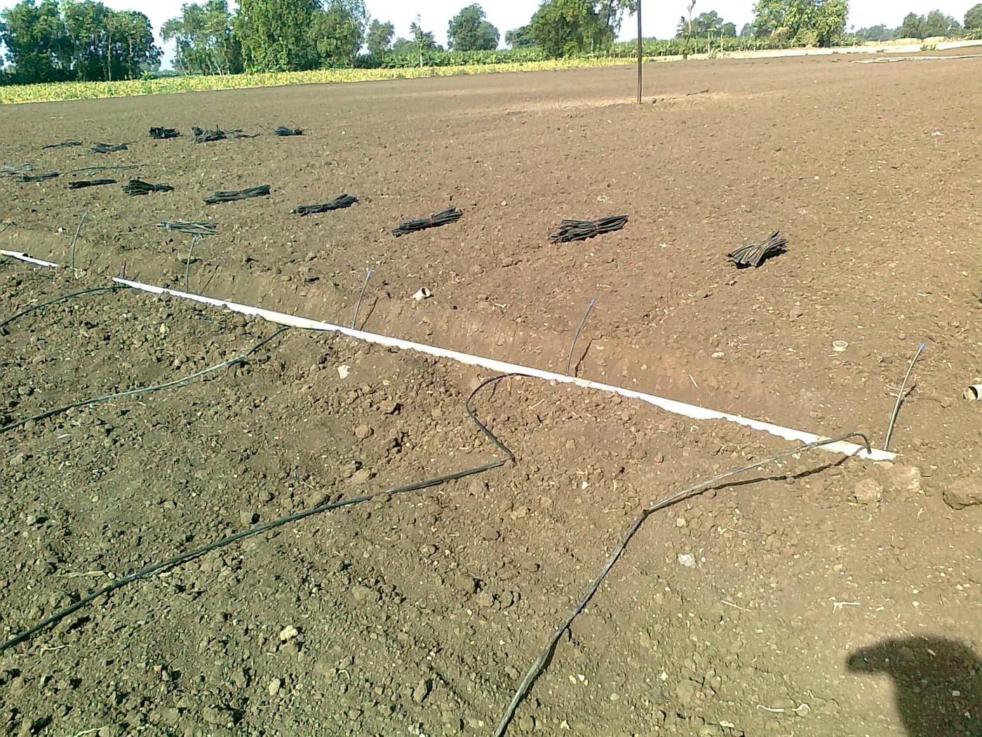
Agriculture irrigation supplies can arrive in the right quantities and still reach the wrong crop block. The person who ordered a tape roll and its fittings may not be the person who later identifies the header, prepares connections or checks the first run. Before work starts, turn the accepted purchase into a field handover that names every block, part option and unresolved connection. A clear handover protects a good order from becoming a set of guessed assemblies. An irrigation parts handover by crop block puts each accepted item beside its destination, so the installer receives the mating decisions behind the order.
Begin with the accepted goods and the actual field drawing. If cartons or item codes have not yet been checked against the order, use the delivery inspection guide first. If the parts list itself is still being designed, the system shopping list handles that earlier decision. This handover starts when the intended parts have been bought and someone else needs to place, connect or later maintain them.
Prepare a drip irrigation supplies handover for the field crew
Put a date and revision on a short map that both buyer and field lead can read. Show each crop block, row or bed group, the header that feeds it, the valve or approved control that serves it, and the location where the new material will be used. Label the drawing with the same block names used on the purchase record. A sheet marked “north vegetables” is less useful if the field crew knows that area as block N3; write both names while the buyer and operator can still agree on them.
Next to each block, list its intended lateral product and selected option, the measured aggregate row length, the number of starts or joins, and the actual parts assigned. Separate an existing item already installed from a new part still in a bag. Mark where a connection must be confirmed rather than drawing it as completed. If the route or active valve groups changed after the order, make the map current before the crew receives parts. The staggered-planting zone guide addresses operating groups as crops change; the packet here tells the crew what has been assigned to the present work.
Keep the selected product instructions with the packet, whether printed or available through a dependable site record. Add the person who can answer field-layout questions and the person authorized to approve an alternative part. A phone number alone is not a technical specification, but an identified decision maker prevents a crew from replacing a missing connection with a similar-looking piece just to keep moving.
Bundle drip tape and verified fittings by crop block
Create a labelled bundle or container for each block with the relevant purchase-line codes and quantity. The bundle may hold small fittings, seals and tags while full tape rolls remain in appropriate protected storage. Put a block label on the container, not across the manufacturer's roll label or an important product marking. Keep factory packaging and instructions with the actual material until the person using it can check them. The new-roll storage guide covers protecting unopened and partly opened rolls between planting dates.
Write quantities in both the selling unit and the piece or metre the crew expects to use. “One roll” is not “one lateral,” and “one bag” is not a known number of connectors unless its current pack contents are confirmed. For each block, record the number of complete sale units issued, any measured length withdrawn from a roll, the individual small parts issued and what remains in shared stock. If the order was accepted for three blocks, do not divide every roll into precut lengths before field measurements and the selected product's preparation instructions are settled.
Use a temporary hold location for an item whose option, count or condition is uncertain. Mark the question on the packet and keep that item out of the ready bundle. A missing label, incompatible delivered size or damaged connector should not be “fixed” by giving it a convenient block name. Once the issue is resolved, note who accepted the exact replacement or correction and update the quantities assigned to that block.
Document each mating pair before a fitting is used
For every planned joint, write the two actual ends and the component intended to join them. Name end A and end B on the map, then record material, product marking, actual dimensions required by the fitting maker, connection style, pressure duty and supporting instructions. A nominal 16 mm label on two packages is a clue for further checking, not proof that their ends mate. The card should point to the named interface on the map, such as “block N3, second tape-to-tape join,” so it cannot migrate to a different job.
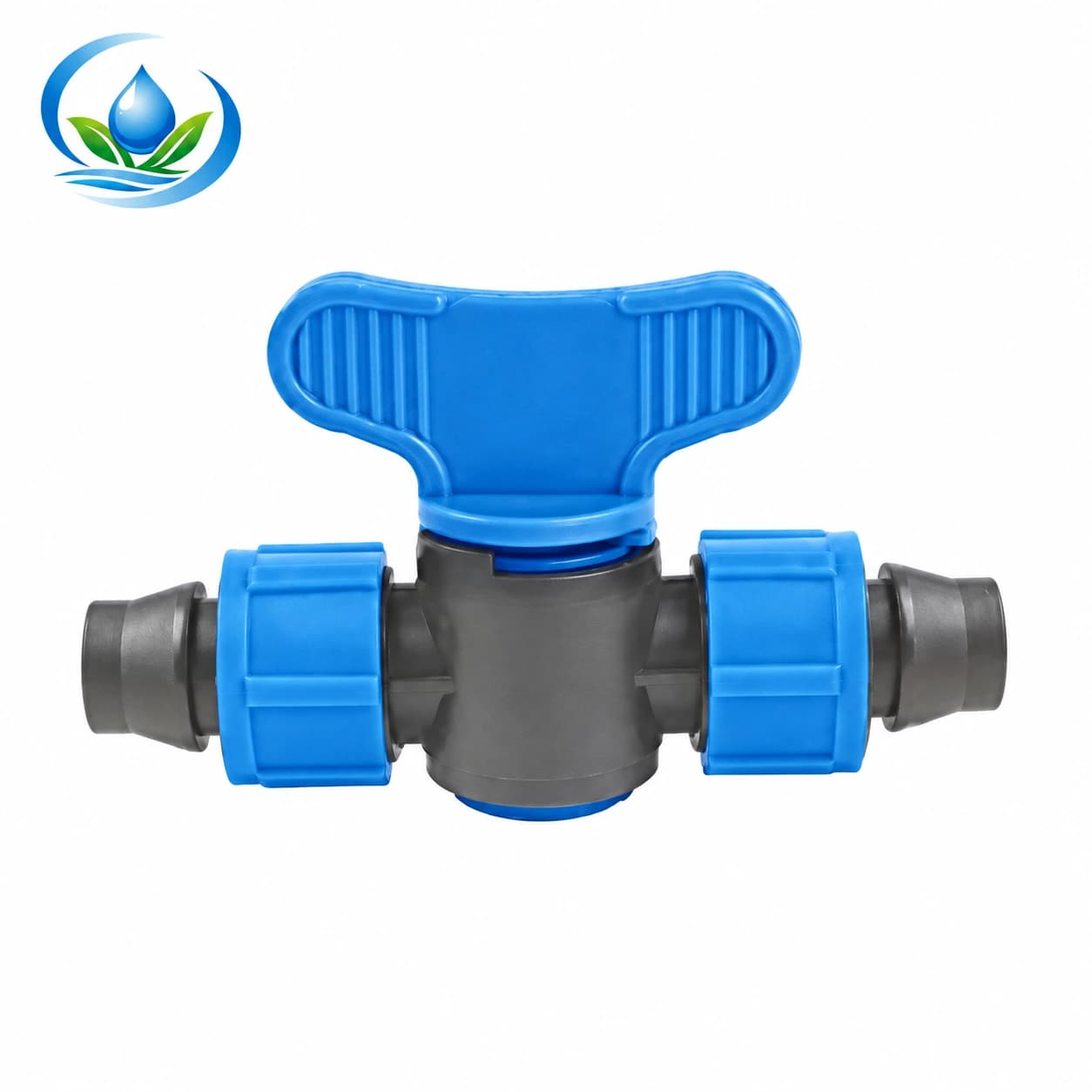
The V161 locking tape coupler valve is described as a 16 × 16 mm tape-to-tape part. It is an example of a part whose two sides have a particular job: joining compatible tape segments with a manual valve at that point. It is not a punched takeoff from a PE header, and its handle does not control other parallel rows fed upstream. Before issuing it for a roll, confirm the actual tape wall and locking fit under the component instructions. Put the confirmed pairing and valve location on the card rather than writing only “16 mm valve.”
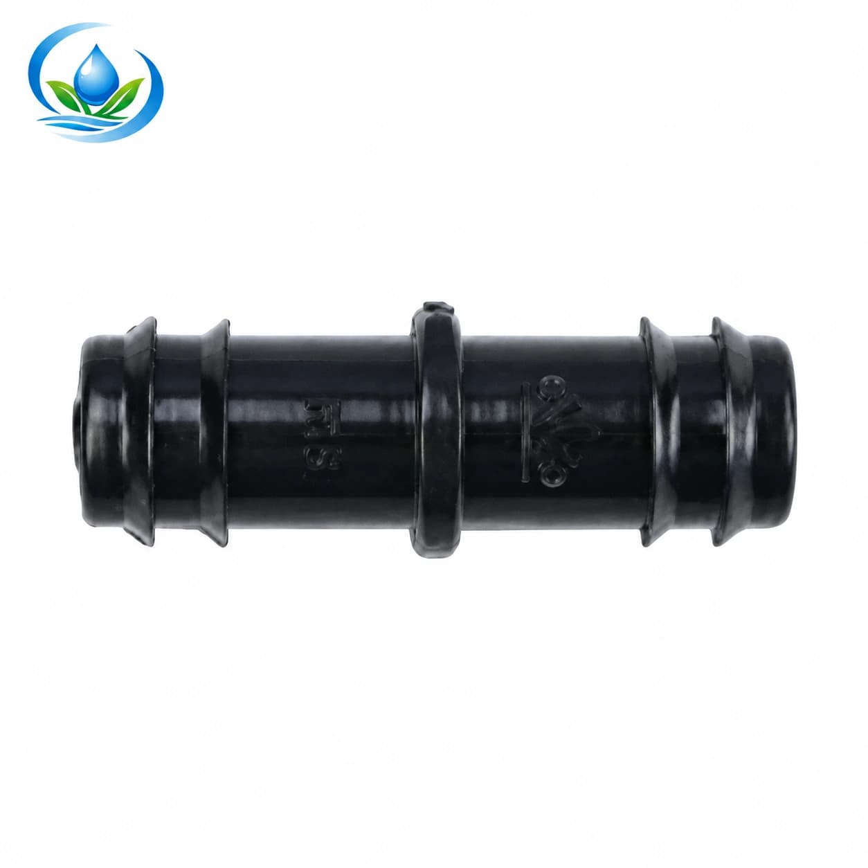
The straight barbed connector has four separate nominal choices: SC0116 for 16 mm, SC0120 for 20 mm, SC0125 for 25 mm and SC0132 for 32 mm. A barb joins the compatible tubing specified for that selected option; the numbers do not make it a tape lock or a header offtake. For a particular blank tube, document both sound tube ends, the connector code, the relevant tube measurements and the maker-approved retention method. Keep that card separate from the V161 tape card even when both carry a 16 mm number.
Show one documented, unpressurized sample of an approved mating pair if the crew will repeat that same joint. Attach a photo of its original markings, the exact component option and the instruction that permits the assembly. The sample demonstrates which physical parts the card names; it does not replace the manufacturer's installation method or prove the operating flow and pressure of the whole zone. If the selected tube or tape, wall or connector variant differs later, hold the new pairing for its own approval rather than copying the first sample.
Keep tape identity separate from its installed layout
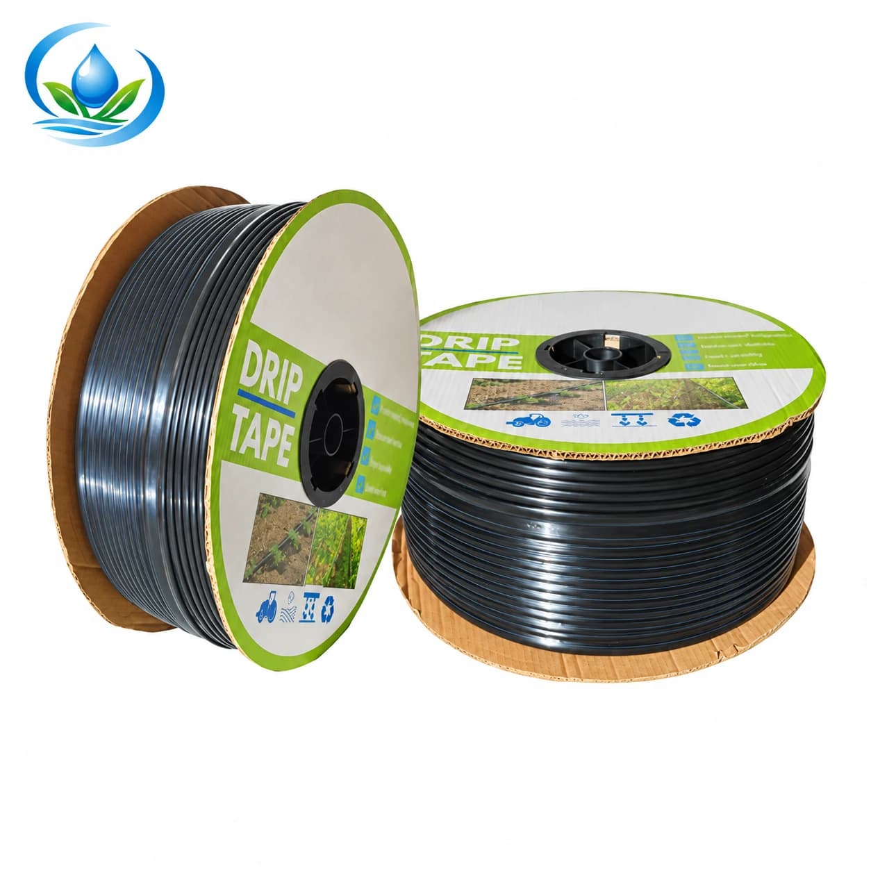
The flat-emitter drip tape includes option IS-2-C526AC2D85, sold as a 2,000 m roll with 16 mm nominal diameter, 0.2 mm wall and outlets spaced 30 cm apart. Those four values help the crew identify the roll and calculate material withdrawals. They do not state the emitter flow for this particular option or authorize a single run as long as the sale roll. Keep the roll's original label visible until its assigned block is finished, and write measured or clearly estimated remainders back into the record.
Draw each intended row on the map and let the approved field design set its installed length, start, end, zone membership and working conditions. A crew should not assume that 30 cm outlet spacing always equals plant spacing or that two rolls with the same width may be swapped between blocks. If a block is added or a row count changes, recalculate the relevant operating case and update the parts map before using the new material. A bundle label cannot substitute for the selected tape's hydraulic information or the farm's actual pressure readings.
Keep proposed connections visibly provisional when their fit is unresolved. A sketch line between the roll and a header may conceal an unselected start, gasket, punch size or transition. Mark those elements as open questions instead of handing over an incomplete assembly as if every piece were present. The outlet-punch planning guide explains why blank PE holes need a confirmed tube, outlet and tool pairing; the tape's factory emitters should not be treated as a blank header to punch.
Give the installer a map of controls and work boundaries
Mark each valve by location and the actual part of the network it controls. Note which block or rows the existing approved operating plan allows to run together. If a V161 sits within one tape run, label the segment downstream of that valve rather than calling it a whole-block control. If several rows share a header, identify the separate control that serves them. Do not assign a valve sequence from the colour or position of a handle alone.
The packet should also say who operates the source and who confirms the particular work area is isolated and depressurized before cutting or opening a connection. Include the site's equipment instructions and approved stop and restart procedure. Confirm the work area is ready before the crew cuts, punches or disconnects any part. The planned line-work isolation guide helps the team describe the work boundary without mistaking a local tape valve for a source shutoff.
For a PE compression joint, an already-cut line can remove the room needed for the selected assembly. The compression-joint guide covers the separate two-end fit and cutting decision. In the handover, identify where that decision is still pending and protect the uncut material. A well-labelled connector in the correct block does not make its fit, safe work state or final assembly automatic.
Close the handover with a walk-through and a short exception list
Lay out the map, block bundles and original labels with the field lead. Ask them to trace one block from its named header to the intended rows and to point to the exact card for a proposed joint. Confirm the quantities issued, who holds the remaining stock, where the instructions can be found and which items are in the hold location. If the first person cannot explain why a given valve or connector belongs in that bundle, correct the label before the crew spreads parts across the field.
Keep an exception list with each unresolved question, the affected block and the person who will answer it. Examples are an unknown tube wall, a missing fitting instruction, an unverified header transition, a changed row length or a product option that differs from the accepted order. Do not quietly replace the specified part with a nominally similar one. Where an exact option or a mating interface is still uncertain, send Store support the selected product code, original markings, photographs and both mating dimensions before buying additional pieces or cutting sound material.
For replenishment, compare the selected options' displayed price, selling unit, current availability and delivery information with the quantities actually missing from the packet. A separate field-spares guide helps maintain a repair box after a system is operating; this handover accounts for the parts already bought for the present installation. Record what was issued and what came back unused so the next planting block does not unknowingly inherit a short bundle.
End with a dated acknowledgement from the buyer or stock keeper and the field lead: map revision, blocks received, accepted option codes, quantity by sale unit and individual item, location of instructions, and the unresolved-fit list. After installation, the crew still has to follow the equipment instructions and observe the finished system under its approved operating conditions. The signoff means both people know what was handed over and where questions remain; the field test will determine whether the installed connections and crop rows perform as intended.
Before you order
Compare this guide with the specifications for your exact product, selected option, water supply and field conditions. Your equipment requirements take priority over a general example.
Compare irrigation products