How to Shut Off Irrigation System Water Before Planned Line Work
Map the source, branch and lateral before opening an irrigation line; check alternate feeds, restart controls and the correct local valve connections.
Published by IrriNex Store
Knowing how to shut off irrigation system water before planned line work starts with naming the exact section to be opened. Stopping one tape lateral, isolating a branch that serves several rows, and stopping the source for a whole installation are different jobs. A reachable hand valve can help with a local job, but its closed handle does not by itself establish that the work section has no other feed or stored pressure. Trace the water path and agree the stop procedure before ordering a valve or cutting a line. Irrigation line isolation before repair begins by naming the work section and confirming that the agreed shutdown covers every feed to it.
Suppose a grower plans to replace a short fitting on a field branch tomorrow. The useful preparation is a marked drawing: where the work is, what supplies that point, which outlets remain active elsewhere, which controls can restart flow, and where the installation permits pressure to be released and checked. That record turns a vague instruction to “turn irrigation off” into a specific handoff between the operator and the person doing the work. It is also the basis for selecting a correctly connected local valve if one is missing.
Isolate the irrigation branch before opening a fitting
Mark the fitting, tube, filter-adjacent connection or lateral end that will actually be opened. Follow the line upstream to its source and downstream to its outlets, noting every tee, loop, tank connection and valve. If an old map is uncertain, walk the visible route and have the responsible operator identify hidden feeds. Write whether the planned work needs the whole source stopped, an entire branch isolated, or only a particular lateral unavailable. The boundary is the portion that must stay without incoming water throughout the job.
Keep the crop side of the decision visible. If one row is taken out of service while neighbouring rows continue, write which outlets can remain open under the existing design and who will operate that group. If the branch is shared, a valve on one tape run will not isolate the other rows. If the work involves a supply manifold, a row-end valve will be in the wrong place. The guide to changing vegetable-row groups helps map which rows normally operate together; the work boundary still follows the real plumbing.
Choose the isolation point by looking at both sides of the intended work. A valve downstream of a fitting leaves that fitting exposed to upstream water. A valve immediately upstream can still leave a section supplied from a far-end loop, elevated tank or connected branch. Two identical-looking handles may control different paths. Label the actual handle and the line it serves on the drawing rather than relying on colour or proximity. If the complete route cannot be established, postpone the opening and obtain the site's layout or competent help.
| Planned work | Water path that must be addressed | Question before parts are ordered |
|---|---|---|
| Short repair on one tape run | That run, plus any alternate feed and retained water | Is a compatible local valve in the correct upstream position? |
| Repair at a branch serving several rows | The whole feeding branch and every connected outlet | Does a reachable branch control match both mating connections? |
| Work beside source or shared headworks | Source, controls, stored energy and all connected paths | What site-approved isolation and pressure-release procedure applies? |
Confirm every feed and stored-pressure path is stopped
Check whether a controller, remote command, timer, pump control or another operator can call for water while the work is underway. Note the actual equipment and the site's authorized way to prevent an unintended restart; simply selecting “off” on one screen may leave another start route or stored energy active. The shutdown sequence for a pump, master valve and source depends on that installation's instructions. Do not close a running pump into a dead end, close its suction while it runs, or defeat an interlock to force a preferred order.
Gravity can matter even when the pump is stopped. An elevated tank, hillside main, full header or loop may continue feeding a lower opening. A downstream emitter can also drain water that was already in the line after its inlet closes. Identify the high points, low points and alternate feeds from the drawing, then ask where this installation directs retained water during planned work. Persistent flow after an ordinary closure is a reason to investigate the route, not proof by itself that the valve failed. The leaking or nonclosing valve guide covers that distinct diagnosis.
Filtration, injection and backflow assemblies may have their own isolation and service requirements. A small manual valve is not a substitute for certified backflow prevention, air or vacuum relief, pressure relief, a pump stop or a documented lockable isolation arrangement. Leave those functions with their exact equipment and qualified procedures. If the work area has an unknown injector, potable-water connection or pressurized vessel, have the responsible operator identify it before the line is opened. Do not loosen a filter bowl or joint merely to find out whether pressure remains.
Make a short stop and verification record for this job
Agree the sequence with the person who operates the system: which source and controls are secured, which identified valve or valves are set, which approved pressure-release path is used, and who confirms that the specific work section is ready. Record the valve labels, work location and date. This is not a universal order of operations; the exact pump, controller, drain and piping instructions decide the actions on this site. A brief signed or acknowledged handoff prevents another worker from restarting an unfamiliar branch while a connection is open.
Pressure may remain after supply is isolated. Use the designated release and verification method for the installed equipment, and keep the work area clear of any discharge route. A gauge can help describe the condition at its own tap, but a zero reading at one location alone does not establish the condition of a trapped or differently connected section. A quiet outlet and dry ground are similarly incomplete evidence. Do not crack a fitting, remove a filter cover or cut tubing as an improvised pressure test; have the competent operator verify the exact section by the approved method.
Record what should happen to irrigation outside the work boundary. If a separate branch may keep serving crop rows, identify its allowed operating combination and the person responsible for it. The smallest-zone pump check explains why a much smaller active group can fall outside permitted equipment operation. A local valve does not automatically protect the pump or regulator when several rows are closed. If the proposed remaining group is not documented as allowed, revise the work window or control plan before keeping it active.
Choose a local valve by its actual two connections
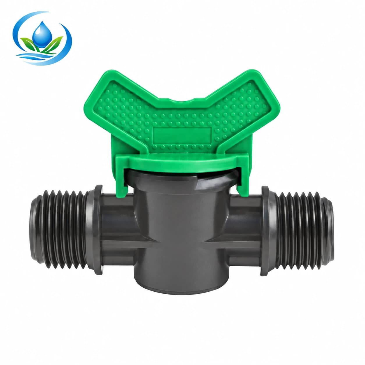
The IrriNex double male thread valve has two listed options: V20E marked 1/2″ × 1/2″ and V25C marked 3/4″ × 3/4″. These are threaded inline connection descriptions for those exact options. They do not establish the mating thread standard, seal type, pressure class or suitability as a complete source isolation device. Identify both existing female interfaces and the full operating conditions, then obtain the matching installation data before purchasing or replacing a threaded valve.
Decide whether a threaded local control would sit where a worker can reach it without putting the work joint on the live side. Leave enough supported, accessible space for the handle and future service. The label “double male” means two male-ended connections, not a universal adapter between all half-inch hardware. An existing female part may have a different thread form or sealing arrangement despite similar nominal size. The PE connection guide helps distinguish a compression joint from a threaded or tape interface before any sound pipe is cut.
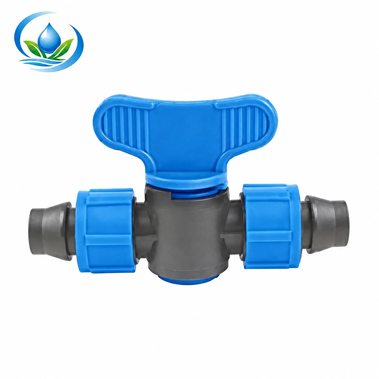
The IrriNex V161 locking tape coupler valve is a 16 × 16 mm tape-to-tape inline connection. It can provide manual control of the downstream section of a compatible tape run when installed according to its maker's instructions. Its two locking ends do not create a punched offtake from a PE header, and the valve cannot isolate a parallel row fed before its position. Confirm the tape's wall and retention fit as well as access to the handle. The work section's other feeds and retained water still need the planned stop procedure.
Decide if the existing control can be trusted for the proposed work
Do not buy a new valve merely because the present handle is inconvenient. Check the installed item's model, location, two connections, condition and the section it actually controls. If water escapes from its body or joint, or a closed position leaves an unexplained continuing feed, that suspect component is not the sole isolation point for opening a line. Arrange a separate dependable upstream control through the site procedure, then investigate the fault. Replacement should follow the cause and verified connection, not the colour of the old handle.
If the present valve is sound but hidden behind the crop or too far from the planned repair, map a new accessible position and verify its fit before making a cut. Count the required adaptors, supported pipe or tape lengths, closures and any replacement of damaged ends. A valve bought alone may leave no correct way to join it to the installed line. The manual valve buying guide compares connection families and quantities; this planned job adds the question of which part must remain isolated during work.
For a line that is only temporarily taken out of service, mark its expected valve state and an agreed re-opening owner. Do not pinch, fold or tie tubing as a makeshift shutoff, and do not assume a cap elsewhere in the workshop fits this line. Record the confirmed component and mating material before preparing any end. If the intended task is seasonal draining or storage rather than a short line change, follow the separate winter parts and drainage guide; a short work stop does not empty every vulnerable cavity.
Prepare the repair and the return to service together
Before the work window, lay out the exact valve or repair fitting, compatible pipe or tape, approved seals or retention pieces, support and identification label. Confirm product option, current price, selling unit, availability and delivery for the selected parts. The V20E/V25C thread choices and V161 tape choice perform different connection jobs; do not order them as interchangeable “shutoffs.” If fit or operating limits are unresolved, bring markings, photographs and the two mating dimensions to Store support before buying or cutting.
Once the operator has confirmed the approved stop and pressure-release condition for the marked section, carry out the line work by the component maker's installation instructions. Keep the open ends protected from soil and identify any removed piece before it is discarded. If unexpected water appears, pause the work and return the isolation question to the operator rather than tightening, cutting or opening more parts under uncertain pressure. A changed branch or valve can alter the later operating case even if the repair itself looks mechanically neat.
Plan the restart handoff before the repair begins. Record who checks the finished joint, who restores the secured source and controls under the equipment's procedure, and which outlets should run in the first observed test. The zone restart guide details broader testing after a seasonal break; for a short job, repeat the appropriate normal operating checks on the disturbed branch and its neighbours. A dry exterior joint is useful evidence, but it does not prove that downstream rows receive their intended water.
Keep the valve map current
At normal operation after the repair, note the open group, working-pressure location if measured, outlet response, leak observations and any drain-down after stopping. Confirm the selected control reaches the intended section, then identify it on a field label and the updated drawing. If a new valve changes the smallest operating group, check that case against the system's approved pump and control range before unattended use. Do not confuse a tested local manual closure with a source shutoff or a permission to open equipment elsewhere.
Keep the accepted product code, both connection specifications, job date, work boundary and the responsible stop and restart contacts with the field record. The next planned repair can then identify where water comes from and which manual valve actually helps, without guessing from a handle photograph. When a source, branch or lateral route changes, update the map before relying on the old stop plan. A good parts purchase leaves an accessible, correctly matched control and a reproducible way to return that exact line to crop service.
Before you order
Compare this guide with the specifications for your exact product, selected option, water supply and field conditions. Your equipment requirements take priority over a general example.
Compare irrigation products