Vegetable Drip Irrigation System: Separate New Plantings from Harvest-Ready Rows
Map newly planted, established, harvest-ready and cleared vegetable rows before choosing tape, inline pipe and manual control for changing irrigation groups.
Published by IrriNex Store
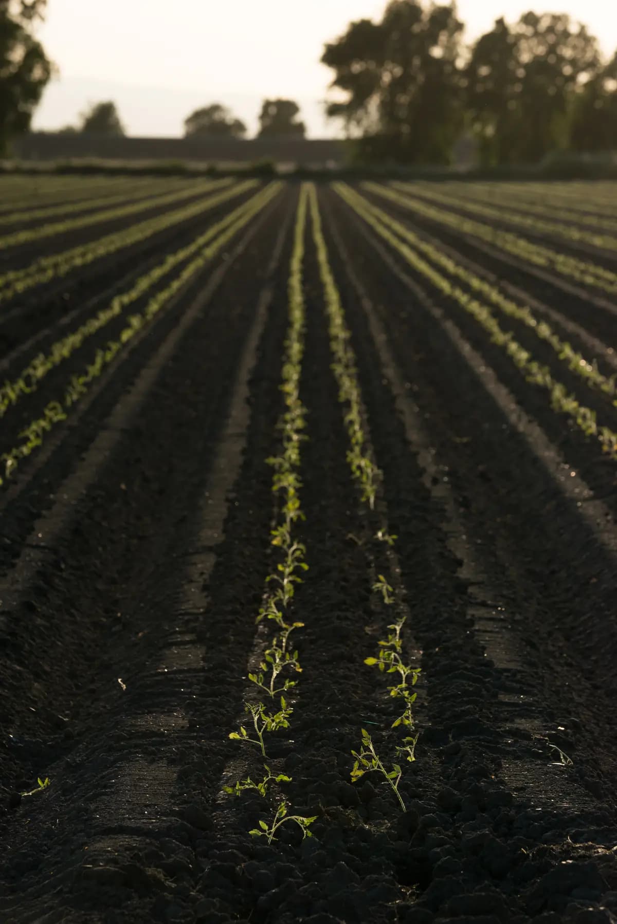
A vegetable drip irrigation system on a market farm may serve rows planted weeks apart from one header. New transplants, established crops, harvest-ready plants and recently cleared rows can occupy the same block on the same day. The useful shopping question is which rows now need independent watering decisions and which outlets will actually run together after the next crop change. Map those states before buying more tape, inline pipe or manual connections. For staggered vegetable drip rows, name the rows that must run together today before deciding whether later planting or clearing needs another valve.
Do not treat a row's label as a watering instruction. “Harvest-ready” does not mean irrigation must stop; a newly planted row does not automatically need a universal number of minutes. Crop condition, local weather, soil moisture in the relevant rooted area and the farm's harvest plan determine the next event. The layout should let an operator act on those observations without accidentally watering an empty row or starving a planted neighbor.
Map staggered vegetable drip rows by planting date
Give each row a stable identifier and draw its connection to the existing header. Beside the ID, record the crop, planting date, whether plants are present, current development stage, intended next field operation and who manages its valve. A row that was planted recently, one still producing, one approaching harvest and one already cleared should appear as separate observations, not as four assumed irrigation schedules. Update the map when the crop changes, not just at the start of the season.
Record soil and exposure differences that might matter more than planting date. An early bed shaded by a structure may dry differently from a later bed on a windy edge; two rows planted the same week may have different cover or mulch. Inspect representative rooted soil positions and the crop before grouping rows under one timing decision. If a field measurement or interpretation is uncertain, keep that uncertainty in the record and use local crop advice instead of deriving a fixed dose from this article.
The map should show what remains physically connected after harvest. A cleared row may retain empty tape, be disconnected for cultivation or be prepared for the next crop. These are distinct hydraulic states. Mark the actual open or closed condition of its valve and the location of any protected exposed end. Do not count a closed, removed row as an active outlet; do not assume that a row called “harvest-ready” has been removed while plants still occupy it.
| Example row state | Question to record | Connection decision to review |
|---|---|---|
| Recently planted | What do local crop and rooted-soil observations support now? | Can this row be watered without forcing the established rows onto the same event? |
| Established | Does its present condition justify the same timing as the new row? | Keep it on a shared group only when the scheduling and hydraulics both fit. |
| Approaching harvest | What does this specific crop still require under local conditions? | Do not close it solely because harvest is near. |
| Cleared after removal | Is the line retained, protected, moved or replaced? | Show its true valve state and the smaller remaining operating group. |
Separate newly planted and harvest-ready row decisions
One shared valve means the connected rows receive the same opening and closing times. If new and established rows need different events, changing the tape outlet spacing does not itself create separate schedules. Decide whether each row needs its own reachable manual isolation point, or whether several rows with compatible present needs can be managed as one named group. The farm zoning guide covers the broader hydraulic layout; this worksheet follows the crop calendar as the membership of that group changes.
Write down the reason for each split. “Row B has a later planting date” is useful background but not proof by itself; “today's crop and rooted-soil observations support a separate event” is a decision that can be revisited. Keep one person or operating instruction responsible for setting the manual valves before the water supply starts. If two groups are ever permitted to run at once, record that explicitly. A vague plan to “open whichever row needs it” is not a reproducible operating arrangement.
Think through the next crop turn before buying the first valve. A row of greens may be cleared while neighboring fruiting vegetables remain; an early row may then be replanted while a later row is still in harvest. The two rows may exchange which one requires closer observation. Place control where it can be reached and identified through a mature canopy and during harvest work. The between-crop bed access guide treats physical access in detail; here access protects the changing irrigation schedule.
Draw the header-to-row connection before choosing a valve
Trace water from the source and existing protection equipment through the header to every lateral. Mark the non-emitting supply line, each branch point, row start, emitting line, manual isolation point and flushable end. Label what each connection joins on both sides. A valve inserted partway along one tape run can isolate the tape downstream of it; it cannot independently control a different parallel row unless the upstream branching is designed to do that.
For separate timing, each controlled row or group needs a supply path that can remain active when another is isolated, within the approved hydraulic layout. The exact transition from a PE header to tape or inline pipe must be specified and checked independently. A tape-to-tape fitting is not a punch-in header offtake just because every label contains “16 mm.” Use the manual valve buying guide to count control points, then verify the actual mating tube, connection method and operating limits for each one.
If the farm already has a header serving established beds, document its current operating case before modifying it. Adding a separately planted row changes the demand whenever old and new rows operate together; shutting a cleared row changes the minimum active demand. The guide to adding a bed to an existing line covers the old-only and proposed combined measurements. Review those allowed groups again when plantings and harvests change.
Compare the exact line options with the row's work cycle
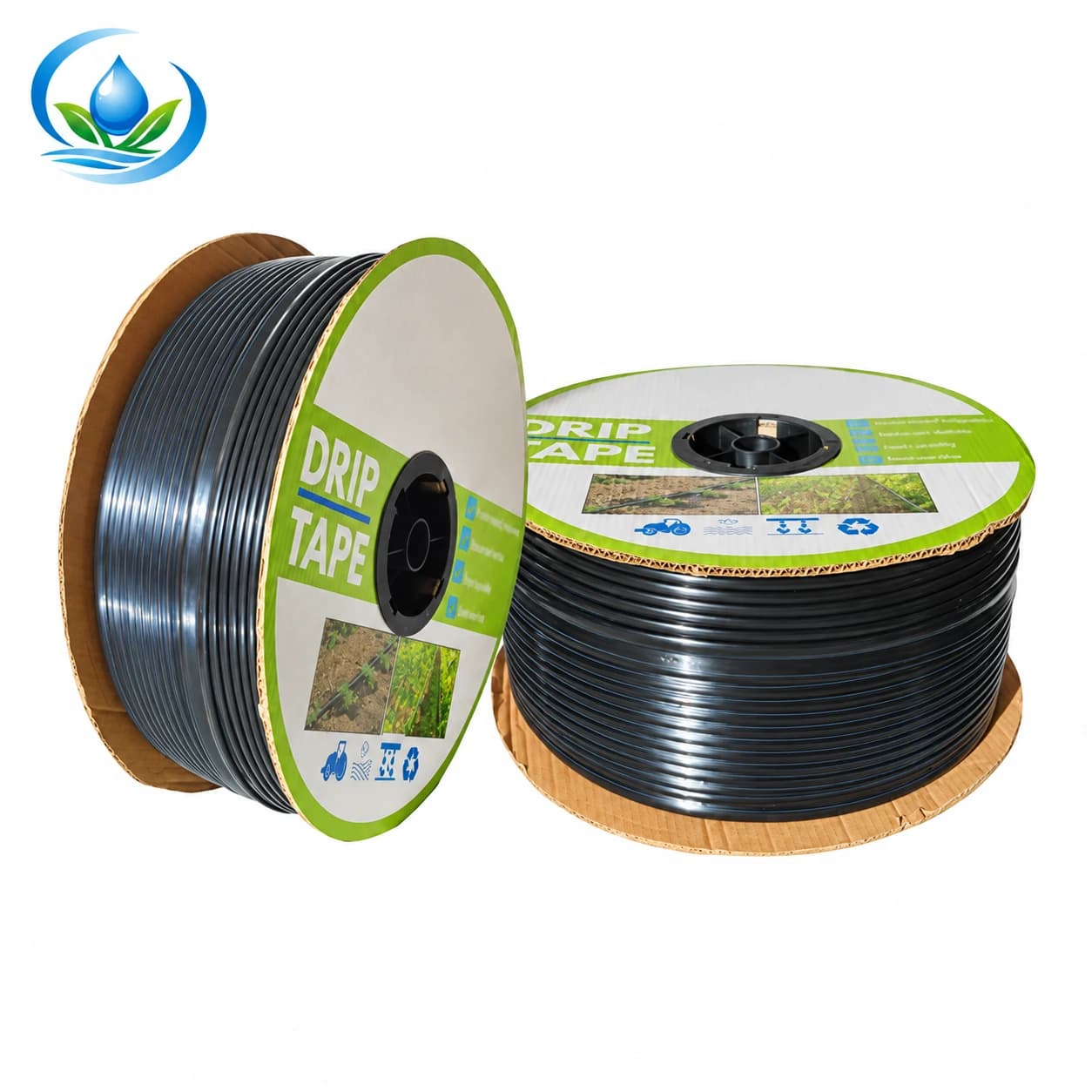
The IrriNex flat drip tape option IS-2-C526AC2D85 comes in a 2,000 m sale roll. Its nominal diameter is 16 mm, the wall is 0.2 mm and outlets are spaced 30 cm apart. These values identify one current product option, not a recommended layout for every vegetable or soil. Before calculating group flow, confirm how much the selected tape's emitter delivers at the working pressure specified for it. Outlet spacing and roll metres alone cannot establish how much an active row draws.
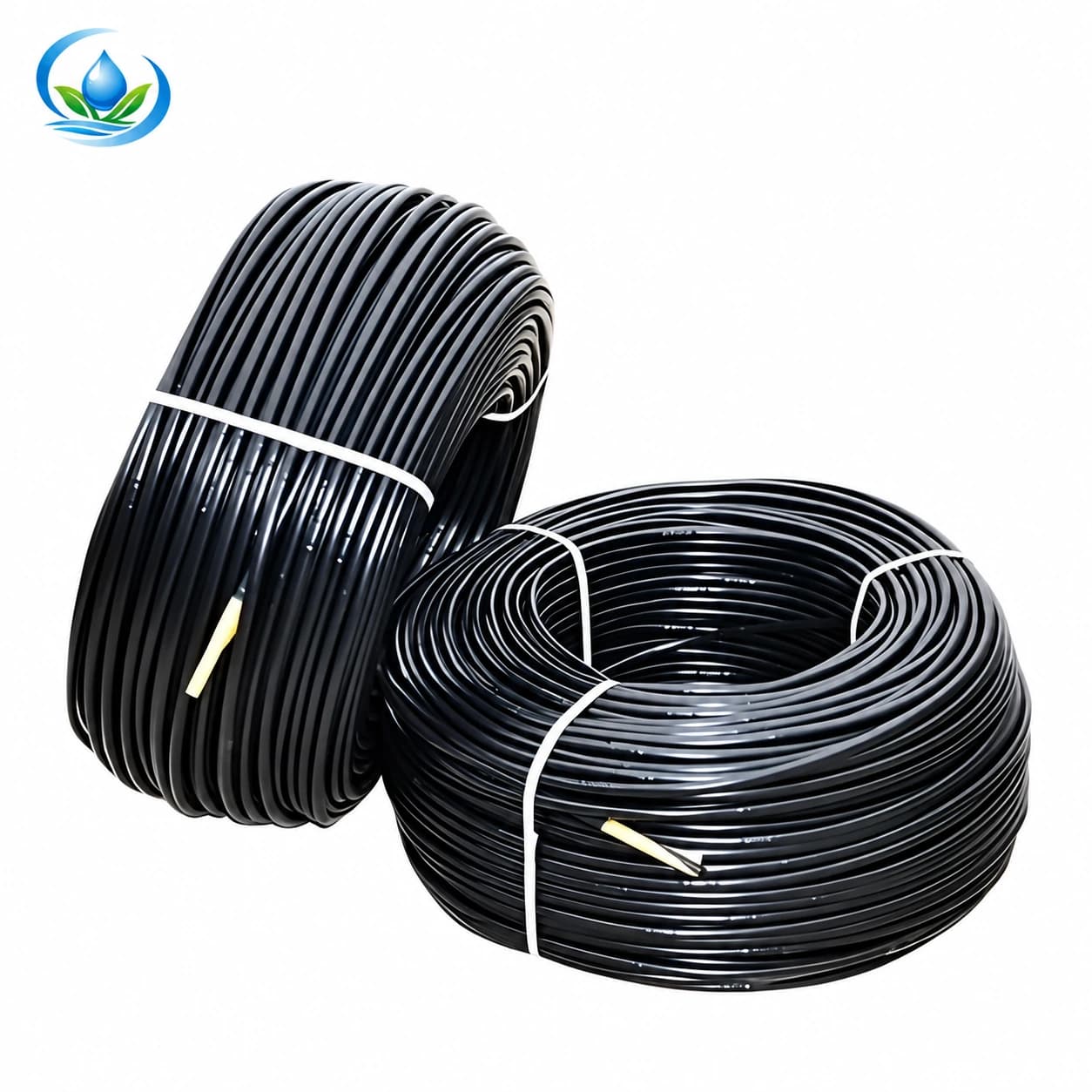
For IrriNex inline drip pipe option IS-3-8CDA6B18CD, a 500 m roll is the sale unit. The nominal diameter is 16 mm; its wall measures 0.8 mm, emitters are 30 cm apart and the listed discharge is 2 L/h at each outlet. That discharge is a nominal product entry, not a measurement at this farm or proof of pressure compensation. Decide whether the material, retrieval plan, location and wetting pattern fit the intended row, then confirm operating pressure and permitted installed length from the exact documentation. Five hundred metres describes a sale unit, not a maximum single lateral.
Do not use a product's fixed 30 cm outlet interval as a universal vegetable plant spacing or a guarantee that a new planting receives enough moisture. Check the actual soil wetting around representative plants and between outlets under the chosen operating case. A later crop with a different root distribution may need a different line position or outlet arrangement. Compare handling as well: tape that will be lifted during cultivation and inline pipe retained through several crop turns create different storage and connection tasks. The build-your-own tape shopping list helps count complete parts, but it is an initial materials basket rather than a staged-crop schedule.
Use V161 for its actual tape-to-tape job
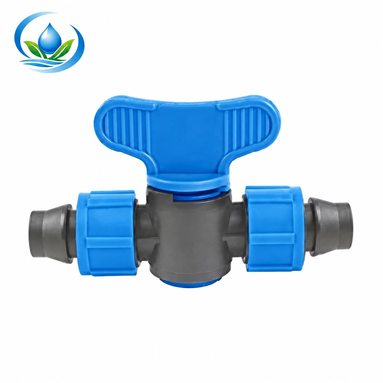
The IrriNex V161 locking tape coupler valve is listed as a 16 × 16 mm tape connection. It joins compatible tape on both sides and can manually isolate a segment of that run when installed according to the maker's instructions. A farm may consider it where one tape run has a downstream section that needs separate isolation. Confirm the selected tape wall and actual retention fit before repeating the joint across rows, and keep the handle accessible.
V161 is not a header punch offtake, a start from a PE main, a pressure regulator or an automatic zone controller. If two vegetable rows run in parallel from a header and need independent timing, draw their separate row starts and suitable valves instead of placing one V161 in a sketch and assuming it controls both. Nor can a valve midway along a tape run keep its downstream plants watered while the upstream part of that same run is shut at its inlet. The topology matters more than the count of blue handles in the basket.
When a harvested segment is truly cleared and its downstream tape is isolated, protect any disconnected end from soil and follow the component instructions for service. Do not pinch or fold tape to create a makeshift shutoff. Keep one labelled diagram at the header so another worker can distinguish a closed crop row from a line whose valve should be open. Manual control changes the water path, not the crop's need or the pressure available elsewhere.
Recheck the smallest and largest permitted operating groups
After choosing which rows can open independently, write an operating-case list for the present planting and the next planned turnover. Include the new row alone if that is allowed, established rows together, any permitted overlap and the smallest group left after a row is cleared. Count installed outlets and lengths only for the lines open in each case. For inline pipe, use the selected outlet's nominal rate as a starting calculation and verify field delivery. For tape, obtain its exact discharge before a numerical group total. The flow calculation guide provides the fuller arithmetic.
A closed row does not make source and pressure requirements disappear. The remaining smallest group must still fit the pump's permitted operation, regulator or meter range and downstream pressure needs; the largest permitted combination must still fit the source, header, filtration and lateral design. A manual valve does not provide automatic protection when those ranges are crossed. Do not close every outlet against a running pump to test a changeover, and do not use a partially pinched tube to regulate pressure. Plan a manufacturer-approved control sequence before the first crop turn.
At normal operation, document the active valves, source condition, header flow if measurable, working pressure and delivery at representative near and far outlets. Compare the new-only, established-only and combined cases only if the system design permits them. Keep the old observation so a later drop at a far row is visible after new tape is added. If a small case or combined case is outside an allowed equipment range, revise the arrangement with qualified help before describing it as a usable schedule.
Buy for the current rows and the next change, then update the map
Make a short order record for every row: crop state and date, proposed line option, actual installed length, connection at the header, any V161 downstream join, compatible end closure, manual valve location and the permitted operating groups. Separate installed quantities from spare roll material. Confirm the exact selected options' current price, sale unit, availability and delivery; a 2,000 m tape roll or 500 m pipe roll does not mean the store will supply a custom cut for one row. Ask Store support about any unmatched interface before buying all the fittings.
Install and test a representative connection under the component instructions before repeating it. Check tape retention, leaks, access after planting and wetting at the actual row; record the expected valve state on the field diagram. After harvest, confirm the plants are actually removed and the remaining rows' schedule still meets local crop and soil observations. Do not treat approaching harvest as a universal stop date or use the previous crop's duration for the next planting. Keep a dated row map and compatible parts list current as the vegetable block turns over.
Before you order
Compare this guide with the specifications for your exact product, selected option, water supply and field conditions. Your equipment requirements take priority over a general example.
Compare irrigation products