How to Add Drip Irrigation for a New Bed Without Starving Existing Rows
Measure the existing rows alone, check the branch fit and combined running demand, then trial the new bed without reducing old-row delivery.
Published by IrriNex Store
To learn how to add drip irrigation for a new crop bed, first record what the existing rows receive while they are the only rows running. The added bed may need just one branch on a plan, but the old and new outlets draw from the same upstream supply whenever they operate together. A tee that fits physically cannot establish that the original crop will still receive enough water.
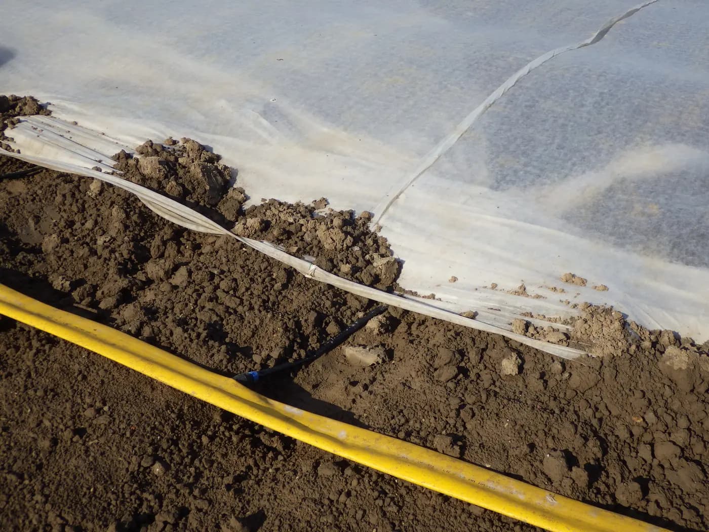
This guide concerns expansion of an existing agricultural drip installation, not conversion from sprinkler risers. The opening photograph shows a real black drip tube fed from a yellow hose into a fleece-covered zucchini bed; the plants are hidden under the cover. It illustrates a crop-bed connection, not the particular IrriNex parts discussed here or evidence of spare supply capacity. The buying decision is whether a labelled, serviceable new branch can be added while the established rows retain their measured delivery.
Record existing-row delivery before adding a new bed
Run the existing rows in their normal permitted configuration, with the filter serviced as instructed and other water uses noted. Label the valve, crop, rows and date. Record source and zone pressure while water is flowing, any available total-flow reading, and observations near the first and last outlets. Where the outlet design permits, compare equal-time collected volumes at representative near and far points. Photograph wetting and any visible leak or blocked outlet. A new-bed drip irrigation branch test should include representative near and far outlets on the established rows before the proposed tee is installed.
Write down the current crop's irrigation duration and the condition under which this record was made. A strong reading on a cool morning may not describe a hot-day source shared with another block. If the old system already has a dry end row, repeated repairs, a loaded filter or an unidentified pressure drop, investigate that first. The new branch should not conceal an existing fault or become an excuse to accept less water for the original crop.
Keep the measured baseline beside the proposed expansion drawing. It is a comparison point, not a guarantee that the supply has unused flow. A static pressure gauge with all outlets shut and a free-flowing bucket at the source do not tell you what pressure and delivery remain at the existing far outlets when both beds run. The crop-zone guide explains broader zone design; here the important test is the change from the old operating case to the proposed combined case.
Give the new bed a named route and operating case
Draw the existing source, filter, control point, blank distribution pipe, emitting laterals and end closures. Mark the new bed as a proposed branch, such as B1, with its own start, crop rows, accessible shut-off position and far end. A mark on the drawing is not permission to cut that pipe. Confirm which tube actually supplies the old laterals and which parts carry emitters.
Measure the new route as it will be laid, including turns around a path and a practical place to service the valve. Mark machinery crossings, foot traffic, mulch edges and places where water or people could disturb a fitting. Keep the branch identification visible after the bed fills with plants. A branch valve hidden beneath a cover may be technically present but difficult to use when one crop must be isolated.
Describe two operating cases: existing rows alone and existing rows plus the new bed. If the crops need different irrigation times, add a third case for the new bed alone. A manual valve can isolate a branch, but it does not provide automatic scheduling or prove that an existing controller can manage separate crop durations. Plan who will change it, when, and how the normal state will be recorded.
Calculate demand without inventing spare capacity
Choose the exact outlets intended for the new bed and obtain their discharge at the specified operating pressure. Count only outlets that would be open in that case. For a simple point-outlet example, planned new demand is outlet count multiplied by the documented discharge per outlet; include any other active delivery devices that share the branch. For inline pipe or tape, use the selected manufacturer's rating basis and the active length. Do not substitute roll length for active outlet count.
When both areas are intended to run together, the upstream pipe, filter and source must carry the combined operating demand. The arithmetic sum is a planning request for a hydraulic check, not a proof of adequate pressure at either bed. Friction, elevation, a loaded filter and the source's actual operating point can change the result. Ask for a review of the proposed flow path, especially the original far row and the new bed's far end.
If an existing meter gives total zone flow, compare before and during a controlled trial under comparable source conditions. A higher total alone is not success: it may coincide with reduced old-row delivery, leakage or uneven new-bed wetting. Keep the drip flow calculation guide beside the exact emitter documentation, and retain the measured old-row baseline so the comparison has a practical pass or fail point.
Identify the actual tube before choosing a tee
Read any marking on the existing non-emitting supply tube and inspect a sound exposed section. Record material, measured outside diameter, wall or inside diameter where needed, condition and any printed pressure information. A nominal 16 mm label does not certify a barb fit to a particular old tube. Weathered or unknown material may need a different repair plan before it can carry a new connection.
Choose the branch point in a suitable blank distribution section, subject to the system instructions and hydraulic review. Do not punch or cut an emitting tape run simply because it is nearest the new bed. Disturbing that run changes the old outlet layout and may leave an unsupported or leaking joint. If there is no accessible blank supply point, resolve an appropriate upstream transition before buying tees. The fittings identification guide helps record the two sides of each proposed connection.
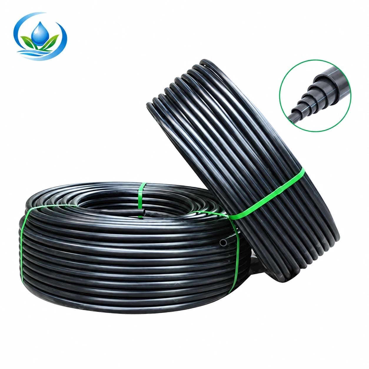
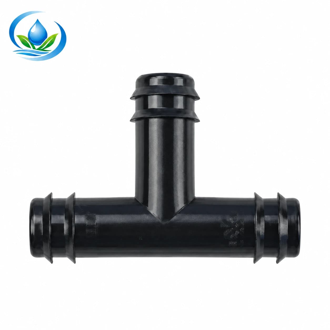
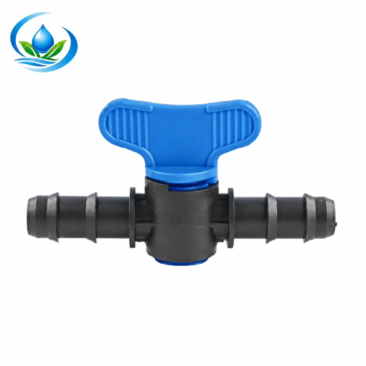
The blank PE tubing, barb tee and manual maxi valve offer component families to review. Their current model entries include two nominal paths:
| Candidate size path | Exact entries to ask about | Required fit check |
|---|---|---|
| 16 mm | Blank PE IS-4-DD62380CF7: 16 mm outside diameter, 1.0 mm wall; tee TC0116; valve V16A1 | Existing tube dimensions and condition, actual barb interfaces, accepted wall/inside dimension, pressure and assembly instructions |
| 20 mm | Blank PE IS-4-9949192827: 20 mm outside diameter, 1.5 mm wall; tee TC0120; valve V20A1 | The same checks for both sides of each join; confirm the downstream transition to the chosen bed lateral |
These rows identify separate catalogue entries, not a certified preassembled tee-and-valve set. A nominal size does not verify that the tee, valve, existing pipe and new pipe seal together. Confirm every interface using the exact pieces and a representative trial. Ask for the quoted price, available quantity and delivery terms of the selected SKUs. No check valve, timer, filter or pressure regulator is assumed to be included with those parts.
Plan an isolated and serviceable installation
Before cutting or opening an existing line, follow the system's shutdown instructions, isolate the affected section and confirm that pressure has been released. Mark the approved cut point, protect open ends from soil and use the installation method specified for the confirmed material and fittings. Do not rely on an improvised under-pressure connection or on a photograph of a similar assembly from another supplier.
Place the proposed manual valve where it can be reached and identified after the crop grows. Allow room to inspect both sides of the tee and to repair the branch without dismantling an old row. Keep a small diagram at the control point showing which branch is normally open. The manual valve guide helps count valves and describe access, but the selected valve's connection and operating limits must be confirmed for this installation.
Flush and start the modified section according to the actual equipment instructions, with sensitive outlets protected as required. Admit water in the prescribed manner, then inspect joints while the intended operating case is active. A branch that looks dry immediately after assembly can still leak, shift or pull away after a full cycle. Arrange a return inspection before treating the expansion as complete.
Test old-only, new-only and combined drip operation
First run the original rows alone and repeat the useful baseline readings. This verifies that the work itself did not damage the old supply. Next, where the control arrangement permits, run the new branch alone and examine near and far outlets, wetted strip and leakage. Finally, run the simultaneous case if that is the proposed normal schedule. Use comparable source and filter conditions and record any other active users.
At each stage, compare flowing pressure, total flow when measurable and equal-time outlet delivery at the old far row and the new bed. Note crop-bed wetting and any changed end-row appearance after a full irrigation event. A single gauge near the source cannot detect every downstream problem. If the original row's delivery falls below the accepted baseline or the new bed remains weak, stop treating the combined case as approved and investigate supply, filter, route, valve and outlet choices.
Operating the beds separately may be practical when the existing source cannot serve both at once or the crops need different schedules. That option still requires checks: the source, regulator, filter and any monitoring equipment must work at each separate operating flow, and the switching procedure must be clear. Closing a manual valve is not a substitute for a documented control plan. If separate operation also fails, revise the design rather than simply lengthening the timer.
Protect the original crop before repeating the purchase
List the exact existing pipe dimensions, selected branch SKUs, proposed bed outlet model, active outlet count, route length, needed closures and any confirmed control or treatment components. Keep unresolved pressure, compatibility and water-quality questions visible on the quote request. Count only joints that the drawing actually needs; do not add a tee to every old row as a generic expansion rule.
Buy or assemble a representative branch first. Compare delivered labels with the approved entries, check both connection sides and retain the old-only measurements. After the trial, write down which operating cases passed, the valve's normal position, any permitted separate schedule and the observations at both far ends. This record will guide later maintenance and prevent a future crew from opening two branches that were only accepted separately.
The crop-row tubing guide helps select the new emitting line after the branch supply is resolved. Adding a bed is complete only when the new crop receives its intended delivery and the original crop still receives the delivery documented before the change.
Before you order
Compare this guide with the specifications for your exact product, selected option, water supply and field conditions. Your equipment requirements take priority over a general example.
Compare irrigation products