Drip Irrigation Zones for Farms: Divide Blocks Without Starving Crop Rows
Divide farm drip irrigation into zones using source capacity, crop demand, row length, elevation and service needs, then select compatible valves, mainline and laterals.
Published by IrriNex Store
Drip irrigation zones are independently controlled crop areas that operate within the available source flow, pressure budget and agronomic schedule. A useful farm zone groups rows that can receive water at the same time and for the same duration without pushing pipe, filters, regulators or laterals outside their operating limits. Dividing by acreage alone misses row length, elevation, emitter output, soil, crop stage and maintenance access. This guide shows how to turn a field map into a zone schedule, calculate demand, decide valve boundaries, select mainline and laterals, and verify that the last rows receive acceptable pressure and flow.
Define a zone as an operating case
A zone is everything supplied when one control valve opens. It may cover one greenhouse bay, a group of vegetable beds, an orchard block or several equal headers. Its boundary should make hydraulic and crop-management sense. A line on a property map is not enough; write down which outlets run, their total demand, target pressure and scheduled duration.
Some farms need sub-zones inside a large block. Reachable row valves allow a damaged lateral to be isolated, but routine operation should not depend on workers remembering a complex pattern. Define the normal valve state and label it on the manifold.
Start with the drip irrigation flow-rate calculation. The simultaneous total becomes the first limit on zone size.
Map crop, rows, elevation and existing supply
Draw the source, pump or tank, filter station, mainline route, headers, rows and flush ends. Record row count, length and spacing. Mark high and low points and measure actual pipe diameters and connection standards. Include roads, machinery crossings and places where valves can be serviced safely. A farm drip irrigation zone layout should identify each valve group and its shared operating case before the mainline and manifold are selected.
Separate blocks with different crop schedules. Young transplants may need shorter, more frequent irrigation than established plants. Greenhouse beds may require a different interval from an outdoor block. Orchard trees and seasonal tape can share a source while remaining on separate valves.
Do not split only by equal area. Two five-hectare blocks can demand different flow when emitter spacing, row length and lateral count differ. The worksheet needs physical layout and product data.
Measure source pressure while the planned drip zone runs
Measure flow and pressure together under a representative load. Static pressure with every valve closed does not show what remains when the zone draws water. For a pump, use an operating point that includes lift and delivery losses. For a tank, consider the lowest normal water level.
Repeat where seasonal well drawdown, shared demand or changing reservoir level affects supply. Design from a dependable condition rather than the single strongest test. Reserve a reasonable margin for filter loading, measurement uncertainty and known operational variation.
If calculated demand exceeds dependable flow, reduce simultaneous rows. If flow is available but dynamic pressure is inadequate at the farthest lateral, review pipe diameter, elevation, zone length and equipment loss before changing emitters.
Group crop rows that need compatible watering schedules
Hydraulics establishes what can run together; agronomy determines what should run together. Group similar crop type, growth stage, rooting depth, soil intake, exposure and desired irrigation interval. A zone controlled by one valve receives one operating duration unless additional control is added.
Avoid combining a high-frequency greenhouse crop with deep-rooted orchard trees just because their total flow fits. One group may be overwatered before the other receives enough depth. Likewise, a sandy section and a heavier soil may need different cycle lengths even with the same crop.
Where a block changes over the season, plan a practical way to isolate harvested rows. The remaining flow must still fall within the minimum range of regulators, meters or injectors.
Calculate the minimum and maximum zone demand
Use the selected lateral variant. For point emitters, multiply active emitter count by flow per emitter. For inline dripline, calculate outlets from active length and spacing, then multiply by outlet flow. For tape specified by flow per length, apply the manufacturer's published basis.
Create at least three cases: the normal full zone, the smallest allowed operating group and the maintenance or flushing condition. Components such as regulators and fertilizer injectors can have minimum as well as maximum flow limits.
Do not count spare roll, closed branches or future rows in the current operating total. Add future expansion as a separate design case so the initial system is not silently operated beyond its documented configuration.
Check pressure variation inside each proposed zone
Build a pressure budget from the source to the most demanding outlet. Include clean and service filter loss, valves, fittings, mainline, header, lateral and elevation. Friction generally increases with flow, so a zone that barely fits the source may still lose too much pressure along its route.
Utah State University Extension's irrigation-uniformity guidance explains that friction and elevation create pressure variation and that inlet conditions outside the original design can change hydraulic behaviour. It recommends monitoring pressure and flow to maintain uniformity.
If the predicted variation is excessive, shorten the zone, divide long and short rows, enlarge delivery pipe where justified, or consider pressure-compensating outlets within their specified range. Do not assume one regulator at the source corrects downstream friction.
Choose a mainline and manifold that serve every case
The mainline may carry one zone or several simultaneously, depending on the operating plan. Size each segment for the largest legitimate combined flow through that segment. A manifold branch carries its own zone demand, while the upstream main carries the sum of valves that are allowed to open together.
Compare the published PE irrigation mainline sizes, then perform the hydraulic check with exact internal dimension, pressure class, route and fittings. A pump outlet diameter is not a pipe-sizing rule.
Keep manifold valves accessible and supported. Label valve, zone name, crop block and normal flow. Provide unions or other service arrangements where equipment must be removed, and leave space for gauges and filter cleaning.
Use row valves for control and repair
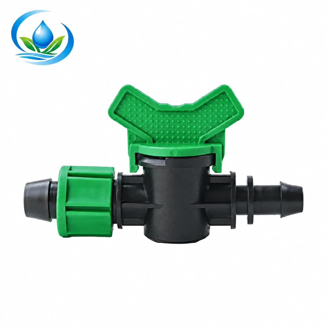
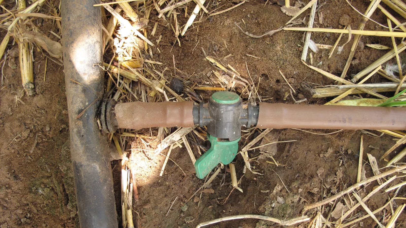
A row start valve lets a lateral be isolated during repair, staged startup or crop change. The 16 mm drip-tape start valve (V16E1) is a published option for compatible laterals. Verify the tape diameter and permitted wall range, header takeoff and punch size before ordering.
Count one start connection per lateral plus appropriate spares. A nominal 16 mm label does not guarantee that tape, round dripline, barb and locking connection share the same geometry. Match the entire connection family.
Do not use row valves to hide an oversized hydraulic zone. If the system only works when workers close an undocumented group of rows, redesign the normal operating cases and control sequence.
Keep filtration and fertigation aligned with zoning
A filter placed before the manifold may need to pass the combined flow of all permitted zones. A filter installed per valve only sees its own zone. In either case, select filtration grade from the smallest downstream passage and capacity from the operating flow with acceptable loss.
Decide whether fertilizer injection serves one zone or several. Each crop may require a different concentration, timing or flushing sequence. The injector must work across the flow range of every connected operating case. Provide backflow protection and follow local chemical-handling requirements.
Record which valves may open during fertigation and how clean water will flush the injector, mainline, headers and laterals afterward. A zone plan is also an operating procedure.
Match lateral type to each crop block
Use a lateral whose spacing, output, wall, pressure range and expected service life fit the crop. Seasonal vegetable rows may favour tape; greenhouse or orchard blocks may favour reusable inline dripline. Calculate each variant separately.
Keep unlike discharge rates out of the same uncontrolled zone unless the runtime and hydraulic design deliberately account for them. Adding higher-flow emitters to a few plants changes total demand and may create a scheduling compromise.
For slopes, separate elevation bands when pressure differences are large. Pressure-compensating emitters can manage variation only within their documented inlet range and cannot protect pipe exposed to excessive pressure.
Build a zone schedule before purchasing
| Zone field | Record | Purchase use |
|---|---|---|
| Rows and active length | Count, length, spacing and crop | Lateral quantity, starts and ends |
| Flow cases | Minimum, normal, maximum and flush | Filter, regulator, meter, injector and valve sizing |
| Pressure | Source dynamic pressure, elevation and loss budget | Pipe diameter, pressure class and outlet choice |
| Control | Valve, sequence and allowed simultaneous zones | Manifold and automation requirements |
| Service | Flush points, gauges, isolation and spares | Maintenance fittings and tools |
Trace every transition from the source to the lateral. Use the agricultural component checklist to catch missing adapters, gauges and flush parts.
Commission zones one at a time
Flush the mainline and header before connecting laterals. Open the first zone gradually, remove air and inspect joints. Record head flow and pressure, filter differential and pressure at representative near and far laterals.
Collect equal-time outlet samples along several rows. A normal total flow can hide a leak balanced by clogged emitters. Compare distribution as well as the head reading. Correct kinks, closed valves, wrong variants and undersized sections before testing the next zone.
Run the smallest and largest approved operating cases. Confirm regulators, meters and injectors remain within their ranges. Store the readings as a baseline for weekly and seasonal comparison.
Avoid common zoning mistakes
- Dividing equal acreage without calculating outlet count.
- Using static pressure instead of pressure under zone flow.
- Combining crops that need different irrigation duration.
- Allowing more valves to open than the mainline design permits.
- Sizing a shared filter for one zone rather than combined flow.
- Ignoring minimum operating flow after rows are harvested.
- Placing valves or flush ends where they cannot be serviced.
Review the zone schedule whenever crop layout, emitter option, valve programming or source condition changes. A previous calculation does not remain valid after the operating case changes.
Frequently asked zone questions
How many rows belong in one zone?
Use dependable source flow, calculated row demand and the pressure budget. The smallest of those limits determines the group.
Can two crops share a zone?
Yes when their timing, application depth, lateral hydraulics and operating pressure are compatible. Similar total flow alone is insufficient.
Does every zone need its own filter?
Not necessarily. A shared filter can serve permitted combined flow and required grade; per-zone filtration may simplify isolation. Design the actual arrangement.
Can row valves replace manifold zones?
They help isolate rows, but routine control should be documented. Manual closures should not compensate for an oversized normal zone.
When should a zone be split?
Split when source flow, pressure variation, crop schedule, equipment range or serviceability cannot be satisfied as one operating case.
Make every zone measurable and repeatable
A practical farm zone has a named valve, defined active rows, calculated flow, pressure target, compatible crop schedule and accessible service points. Its materials come from the worksheet, and its performance is confirmed at the head and the farthest rows.
When requesting a compatibility review through IrriNex Store support, send the zone schedule, field drawing, source test, elevation, selected lateral options and allowed valve combinations. That evidence produces a useful product comparison and leaves the farm with a design record that can be maintained.
Before you order
Compare this guide with the specifications for your exact product, selected option, water supply and field conditions. Your equipment requirements take priority over a general example.
Compare irrigation products