Agricultural Drip Irrigation System Components: A Field-Ready Shopping List
Build an agricultural drip irrigation system from measured field requirements. Compare head-control parts, PE mainline, dripline, filters, row valves and the small fittings that keep installation moving.
Published by IrriNex Store
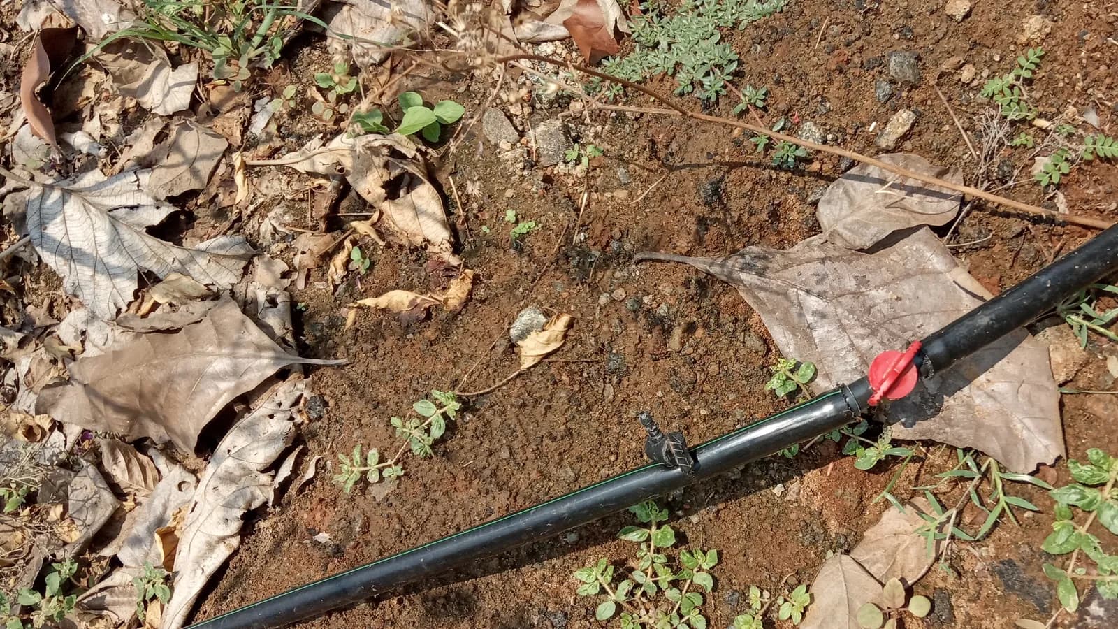
A drip irrigation system for a farm is a measured chain of components, not a pile of parts selected by nominal size. A field-ready system normally includes source protection, filtration, pressure control, a mainline and headers, zone and row valves, compatible fittings, drip tape or inline dripline, flushable ends, gauges and the tools and spares needed for commissioning. The right shopping list begins with zone flow, operating pressure, water quality, row length and connection standards. This guide turns those field facts into a practical order list for row crops, greenhouses and orchards.
Start with a field worksheet, not a product photo
A component can be well made and still be wrong for a particular block. Before opening product pages, draw the water route from the source to the last emitter. Mark the pump or pressurized supply, filter station, mainline, each header, the rows controlled by each valve and every change in elevation. Add the dimensions of existing connections. This sketch exposes missing transitions before installation day.
Record the following values for every zone:
- Row count and length: these determine the total lateral length and the number of row starts, valves and end closures.
- Emitter spacing and flow: use the exact selected product option, not a family-level assumption.
- Simultaneous zone flow: multiply the flow per emitter or per length by the quantity operating together, then include a reasonable design allowance.
- Dynamic pressure: measure pressure while water is moving at a useful flow. Static pressure alone does not describe field performance.
- Elevation change: map high and low points because pressure changes with terrain.
- Water source and debris: note sand, silt, algae, organic matter and known mineral deposits.
- Pipe and thread standards: measure actual pipe outside diameter and identify BSP, NPT, flange, hose or other interfaces.
The worksheet is also the basis for asking useful pre-sale questions. “Will this fit my system?” is difficult to answer. “Will the 32 mm outlet connect to my measured 32 mm PE pipe, and is the thread BSP or NPT?” can be checked.
Map drip irrigation components from inlet to row end
Thinking in water-flow order prevents forgotten parts. A common agricultural arrangement is source or pump, source-protection devices, filtration, pressure and flow monitoring, pressure control where required, fertigation equipment if used, mainline, zone manifold, headers, row starts, laterals and flushable ends. The exact order changes with the pump, filter design, injector, valve type and backflow rules, so follow the equipment manuals and local requirements. A drip irrigation system parts list should show which connection joins each neighboring part, not merely name the parts in water-flow order.
Do not hide service items where they cannot be reached. A disc stack needs clearance for removal. A gauge needs to be visible while a zone runs. A row valve should be reachable without walking over the crop. Flush points belong where dirty water can leave the system without flowing back across the bed.
Penn State Extension describes the same agricultural system as six broad groups: delivery, filters, pressure regulation, valves and gauges, chemical injection and controls. Its detailed guide to drip irrigation for vegetable production also explains why water source and emitter choice change the required filtration. Use that framework to check completeness, then use the actual product specifications to select each part.
Select the mainline and headers from zone demand
The mainline carries the combined flow from the source toward one or more zones. Select it from calculated flow, route length, allowed pressure loss, pressure class and installation conditions. A larger diameter generally reduces friction loss, but diameter alone is not a complete design. Fittings, valves, elevation and long routes add losses, while an oversized pipe may add cost and handling work without solving a poorly divided zone.
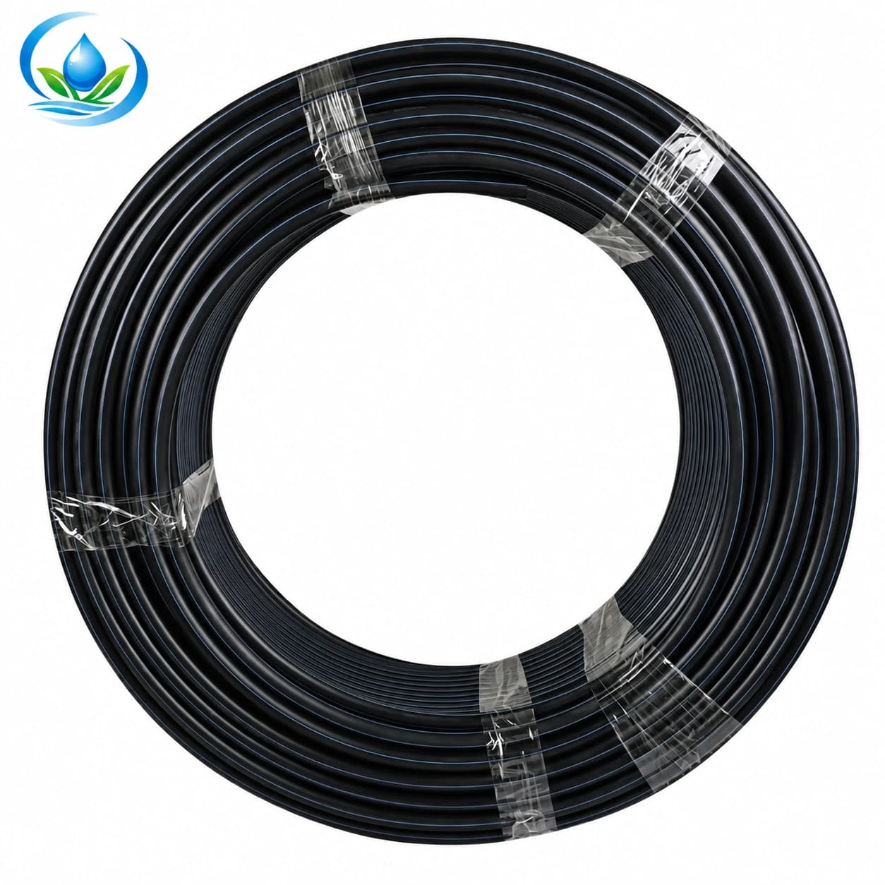
The IrriNex Store PE irrigation mainline pipe family lists 32–160 mm options. Confirm the diameter and pressure class of the exact option you intend to order. Then match every tee, elbow, adapter and valve to that option. Do not assume that two products carrying the same nominal millimetre label share the same wall series or joining method.
A header distributes water across the starts of several rows. Depending on the farm, it may be rigid PE, flexible layflat hose or another compatible product. Count all takeoffs before ordering. Add an accessible isolation valve for each zone and a flushable end for the header. If machinery crosses the route, plan protection and seasonal removal before choosing the material.
Choose inline dripline or drip tape by crop cycle
The lateral is the component that delivers water beside the crop. Thin-wall drip tape is commonly used for straight seasonal rows. Round inline dripline is more robust for repeated use, greenhouses, orchards and routes that need more handling. Neither choice is universally better; the purchase must match the crop cycle, terrain, operating pressure, retrieval plan and cost per season.
| Selection question | Drip tape | Inline dripline |
|---|---|---|
| Typical use | Straight annual crop rows and seasonal installation | Repeated-use rows, protected crops and permanent planting |
| Options to verify | Diameter, wall thickness, outlet spacing, flow per length and roll length | Tube diameter, wall, emitter spacing, emitter output and pressure behaviour |
| Required fittings | Tape-specific locking starts, couplers, valves and ends | Barbed or mechanical fittings sized to the actual tube |
| Field risk | Twisting, stretching, excessive pressure and sharp folds | Kinks, wrong fitting engagement and excessive pressure loss on long runs |
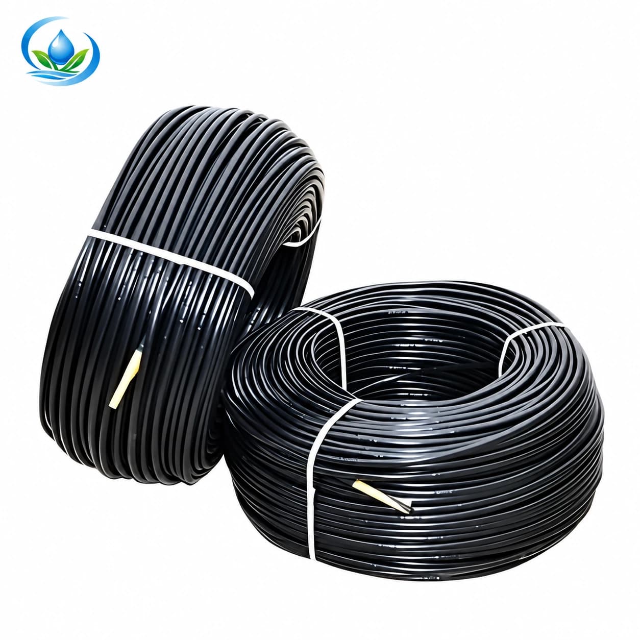
For a reusable lateral, review the 16 mm inline dripline options. Compare emitter spacing and output with the plant layout, and calculate how many metres can run in one zone within the available flow. For seasonal rows, browse the drip tape category and treat wall thickness, spacing and flow as separate decisions. Do not buy by roll length alone.
Make filtration a design item
Filtration protects every small water passage downstream. Choose it from the water source, contaminant type, required filtration grade, zone flow, pressure rating, clean-filter pressure loss and cleaning method. A small connection that happens to fit the pipe can still restrict the zone or require constant cleaning.
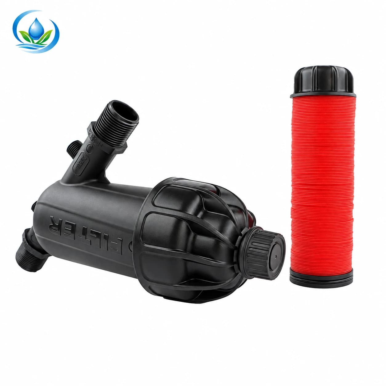
Screen filters are often practical for relatively clean water with limited inorganic particles. Disc filters provide a grooved, three-dimensional path that can hold a mixed debris load and can be cleaned by separating and washing the discs. Surface water with heavy algae or organic material may require staged treatment or media filtration beyond a small inline unit. Sandy well water may need separation before fine filtration. Have the water assessed when the source is uncertain.
The Y-body disc filter is a useful retail option for appropriate flows and water conditions. Before adding it to the cart, select the connection size and filtration grade, then compare them with the lateral manufacturer’s requirement. Check whether the listed flow is compatible with the whole zone and leave room to remove the disc element. Install gauges on both sides of a larger filter station so an increasing pressure difference can signal cleaning time.
Control pressure with measurements
Drip tape and emitters operate within specified pressure ranges. Excessive pressure can open connections, damage thin wall tape or change discharge. Too little pressure can leave distant outlets under-supplied. A regulator only reduces pressure when used within its design flow and installation conditions; it cannot create pressure that the source does not provide.
Use a gauge near the control head and, during commissioning, measure at the start and end of representative laterals. Compare those readings with the exact lateral specification. If the far end is low, investigate zone flow, mainline diameter, clogged filters, elevation, lateral length and undersized fittings before assuming the regulator is faulty.
Valve placement also matters. Some regulators are intended for flowing conditions and should not sit under continuous static pressure. Fertigation equipment changes the head-loss calculation and may require a controlled bypass. Follow the regulator, injector and valve manuals rather than copying a small garden head assembly into an agricultural installation.
Count every row connection and service part
Large parts are easy to remember; installation is more often delayed by one missing adapter, punch or end closure. Count connections from the drawing, then group them by interface. For each row you may need a header takeoff, gasket or grommet, feeder, start fitting or valve, lateral and reopenable end.
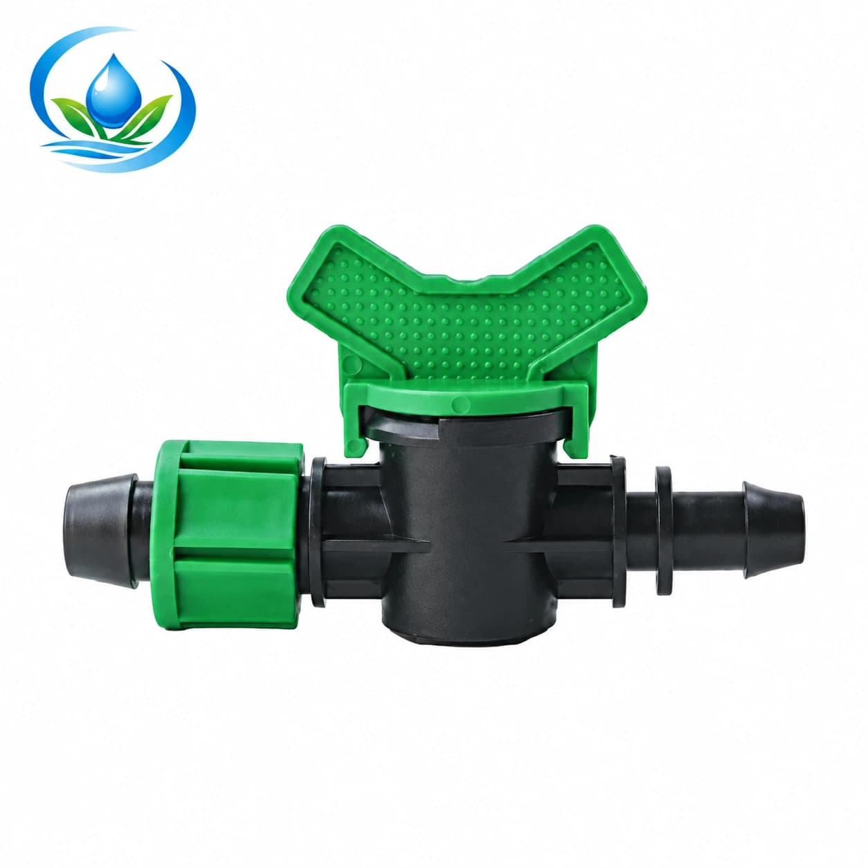
A 16 mm row start valve (V16E1) can isolate an individual lateral for scheduling or repair when it matches the tape interface. Check whether the 16 mm label refers to the lateral connection you have selected. If a takeoff passes through layflat or a PE header, verify the hole size and seal specified for that fitting. The punch must match the takeoff; an approximate hole can leak even when the valve itself is correct.
Add practical spares. A field kit should include several couplers, row starts, end closures, gaskets, plugs and the correct punch, plus a clean cutter, thread-sealing material suitable for the specified threaded joints and a gauge. Spares should match the installed connection family. A box of unrelated “16 mm” pieces is not a repair kit.
Turn the field worksheet into a crop-row components list
| Component group | Quantity basis | Specification to record |
|---|---|---|
| Source connection and protection | One set per supply point | Interface, pressure, backflow or source-protection requirement |
| Filter or treatment train | One sized station per operating flow | Water condition, filtration grade, clean flow and pressure rating |
| Pressure and flow instruments | Head unit plus field test points | Range, connection and accuracy suitable for the system |
| Regulator or pressure-control valve | Per zone or control design | Outlet pressure, required flow range and static-pressure rating |
| PE mainline and header | Measured route plus installation allowance | Outside diameter, wall or pressure class and joining method |
| Zone valves and fittings | From the hydraulic layout | Connection type, bore, direction and pressure rating |
| Row starts and valves | One per lateral, plus spares | Header interface, hole size and lateral size |
| Drip tape or inline dripline | Total row length plus repair allowance | Diameter, wall, spacing, flow, pressure range and roll length |
| Flush ends | One per header and lateral | Reopenable style and matching connection |
| Tools and repair parts | One field set plus compatible spares | Punch size, cutter, gauges, plugs, couplers and seals |
Write the selected product option beside every line. A product-family name is not enough when several diameters, filtration grades or emitter spacings share one page. Save screenshots or an exported order list so the installed system can be repaired with the same specifications next season.
Check compatibility before checkout
- Complete the flow calculation. Confirm that the source, filter, mainline and control parts can serve the simultaneous zone demand.
- Trace every transition. Read the drawing from source to lateral and name the exact fitting between unlike parts.
- Verify actual dimensions. Record pipe outside diameter, tape or dripline size and thread standard.
- Confirm pressure at the product level. Compare working pressure and test pressure with the selected option, not a nearby item.
- Match filtration to the smallest passage. Use the lateral or emitter requirement and allow for the real water condition.
- Plan cleaning and flushing. Make every filter element and line end accessible.
- Add commissioning instruments. At minimum, arrange a reliable way to measure operating pressure at the head and at representative laterals.
If an interface is unclear, use the product support form before ordering. Send the product links, chosen options, pipe measurements, thread photographs, zone flow and pressure. That evidence allows a compatibility check without treating a product photo as a technical drawing.
Commission one zone before scaling up
Install and test one representative zone before repeating the layout across the farm. Flush the mainline and headers before connecting the laterals. Connect the rows, open the ends and flush again. Close the ends, bring the system to operating pressure slowly and inspect every transition.
Measure pressure at the head, the start of a representative lateral and its far end. Check discharge from several outlets rather than judging by wet soil at the nearest row. Look for twisted tape, kinked dripline, poorly seated takeoffs, filter pressure loss and connections that move during startup. Correct the cause before installing the remaining blocks.
Create a maintenance record with clean-filter pressure readings, flushing dates, repairs and the part numbers used. The record makes seasonal recommissioning faster and helps distinguish a clogged filter from a changing water source or an undersized zone.
Frequently asked buying questions
Can I choose the pipe diameter from the pump outlet?
No. The pump outlet is only one interface. Size the route from zone flow, distance, pressure loss, elevation and pipe pressure class, then add the transition required at the pump.
Does every agricultural drip irrigation system need a pressure regulator?
It needs pressure within the lateral’s operating range. Some systems achieve that through pump control or zone valves; others use a regulator. Measure dynamic pressure and follow the selected equipment specification.
Is a disc filter always better than a screen filter?
No. The useful choice depends on contaminant type, load, required grade, flow and cleaning plan. Disc filtration is strong for many mixed loads, while a screen may suit relatively clean water. Difficult surface water may need more treatment than either small unit can provide.
Should row valves be installed on every lateral?
They are useful when rows need isolation, staged startup or individual repair. The extra cost may be unnecessary in a small uniform block, but the decision should be made before counting takeoffs.
How many spare fittings should I order?
Base the spare quantity on field size, failure consequence and lead time. Keep enough compatible starts, couplers, ends, seals and plugs to repair several rows without stopping an irrigation cycle.
Build the order around evidence
A dependable drip irrigation system starts with measured demand and ends with a documented, compatible parts list. Calculate each zone, choose the lateral, size the delivery path, protect it with appropriate filtration and pressure control, and count the small service parts from the drawing. Then commission one zone under operating conditions.
Use the IrriNex Store product catalog to compare published options and the earlier introduction to IrriNex Store to see how product specifications and support are organized. When the dimensions or operating conditions do not line up clearly, pause the order and verify them. That short check costs less than rebuilding a header in the field.
Before you order
Compare this guide with the specifications for your exact product, selected option, water supply and field conditions. Your equipment requirements take priority over a general example.
Compare irrigation products