Irrigation Pipe Fittings: Connect a Filter Outlet to PE Mainline
Specify a complete filter-to-PE adapter chain by checking port gender and thread, compression grip, pipe OD, service removal and pressure test.
Published by IrriNex Store
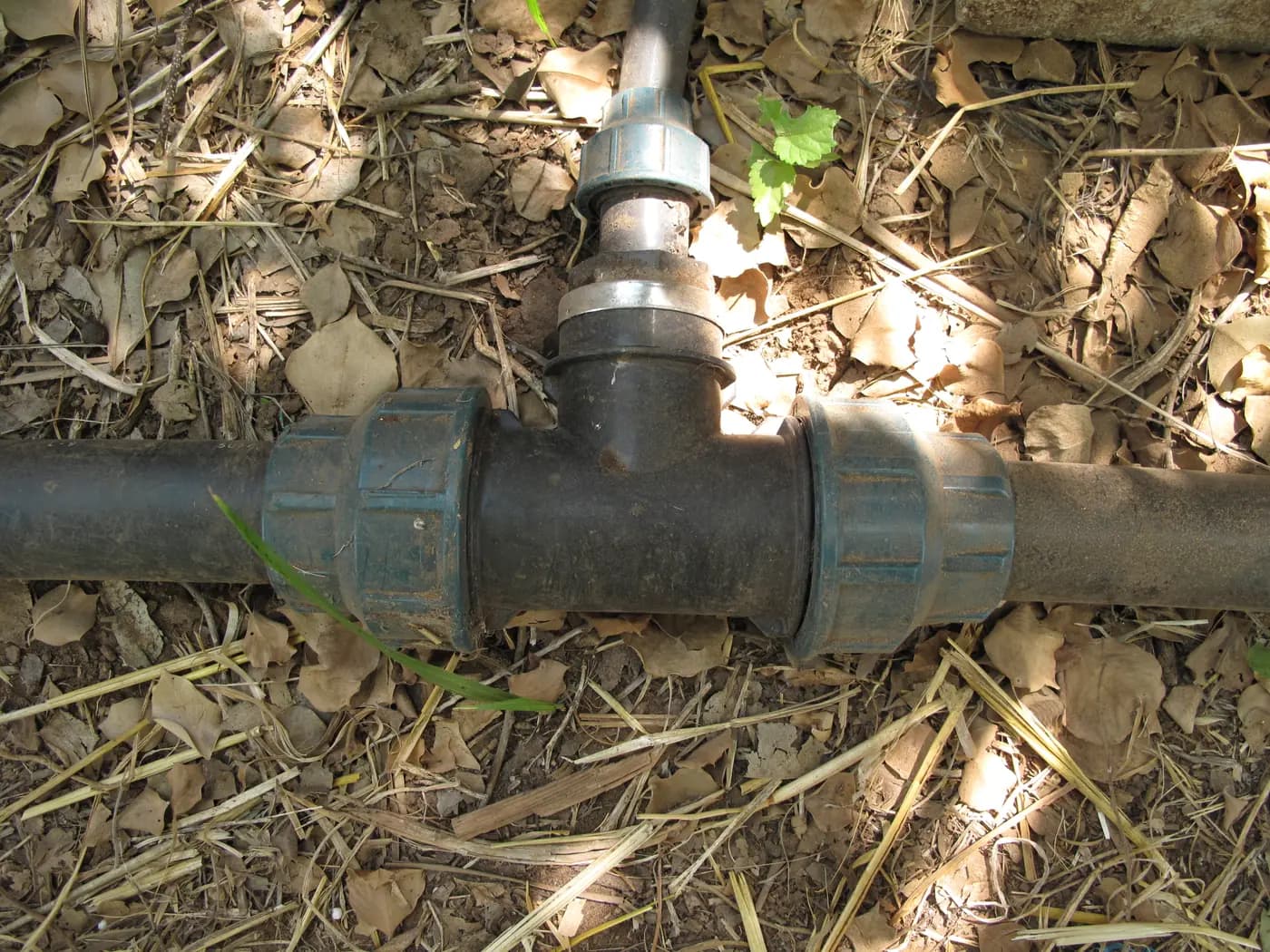
Irrigation pipe fittings are easy to misorder when a filter outlet, a threaded adaptor and PE main pipe are described only by one matching inch number. The filter port needs its own verified gender and thread standard; the adaptor has a threaded end and a compression end; the PE pipe is specified by outside diameter and pressure class. Build the connection as a complete chain on paper before cutting a pipe. A nominal 1-inch port on a filter and a 32 mm pipe are not proof that a photographed 32 × 1-inch adaptor will seal between them.
This guide follows one filter-to-pipe transition from the body outlet to the first supported mainline section. It is different from the thread identification guide, which checks a loose mating pair, and the compression coupling guide, which joins two known PE ends. Here the buyer must account for the filter port, thread interface, adaptor, pipe, support, service removal and pressure test as one assembly. If a link is unverified, the chain is not ready for a cart.
Record the filter outlet without assuming its thread
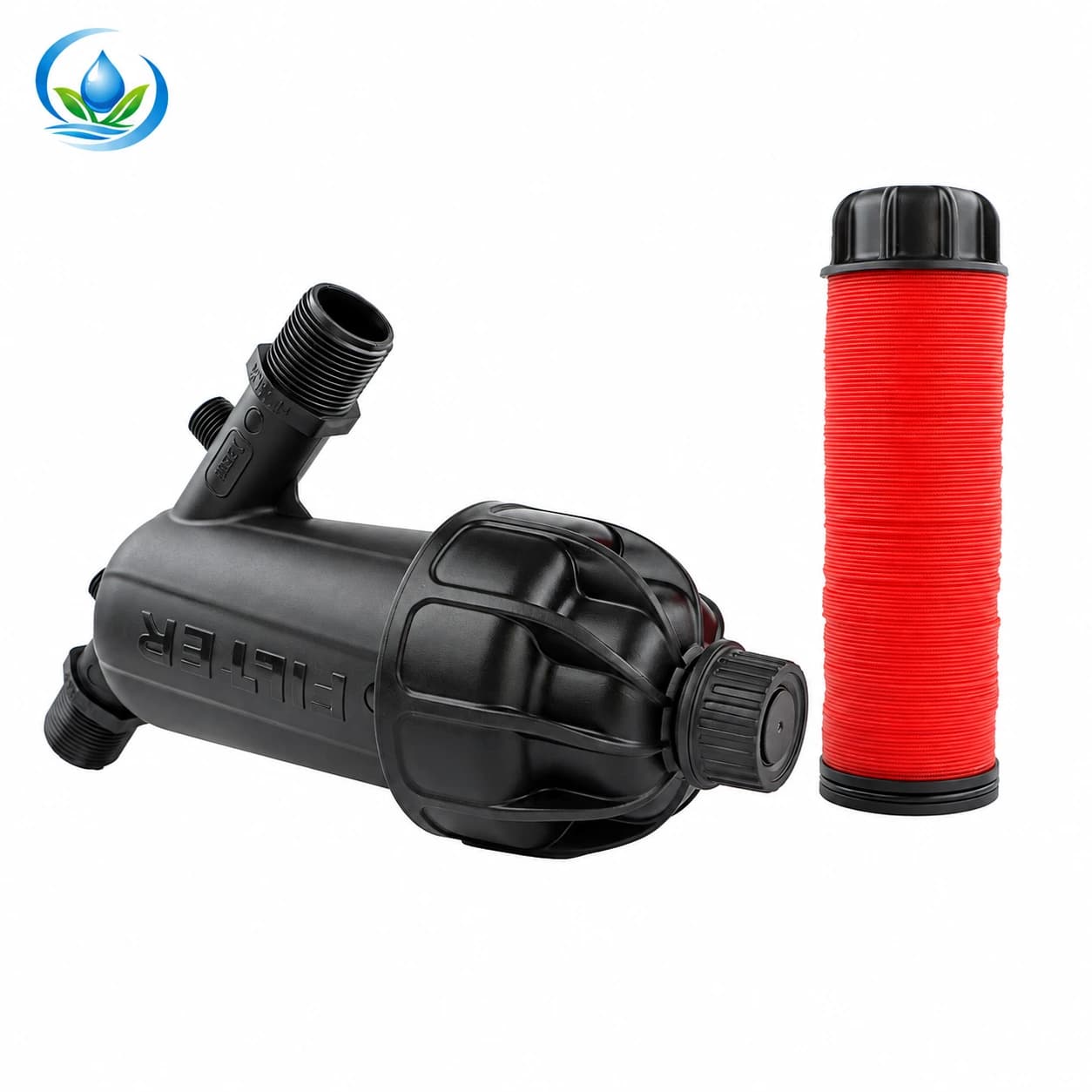
Start with the exact filter option, not just the family name. The published Y-body disc filter has option labels including F32YD at a nominal 1-inch connection, 120 mesh, maximum listed flow 6 m³/h and maximum listed pressure 8 bar. Those numbers belong to the option as listed; they do not identify the outlet's thread standard or whether its port is male or female. The page also does not supply a pressure-loss curve for this proposed mainline. Request an option drawing or manufacturer's connection detail before choosing the mating adaptor.
Photograph the actual filter body or the delivered option from several angles. Capture flow arrow, outlet marking, any thread label and enough scale to measure. Determine whether the outlet is threaded, flanged or another joint and whether it seals on a thread, washer, O-ring or another specified surface. Do not force a male part into a look-alike female thread to “see if it goes.” Different standards may begin to engage yet fail to seal or damage the plastic body. An existing site's connector may also hide the original port, so inspect the filter itself where safe.
Mark the filter's intended service orientation on the drawing. A removable element needs room to leave the housing, and an isolation or union arrangement may be required to open the body without twisting a long PE main. If an adaptor is glued, threaded or clamped where it prevents future removal, a mechanically connected filter can still be a poor installation. The filtration buying guide covers grade and water-source selection; this article assumes the selected filter already meets that duty and focuses on its outlet connection.
Specify the adaptor as two independent ends
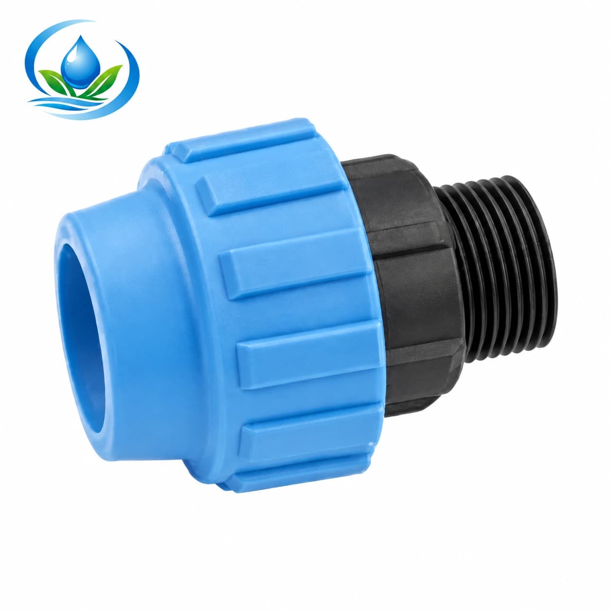
The H-compression male adaptor family includes a listed 32 × 1-inch option, as well as several other pipe-outside-diameter and thread-size combinations. The first number is a candidate compression side for a matching PE pipe; the second labels the male threaded side. The label alone does not establish thread form, seal method, pressure rating or compatibility with the Y-filter port. Confirm those from the exact model information and the filter outlet drawing. If the filter outlet is not the correct female mate, choose a different approved connection, not extra sealant or more force.
Use a connection schedule with one row per interface. For the filter side, write exact filter code, outlet size, gender, thread standard, seal type and its approved orientation. For the adaptor side, write exact adaptor code, male thread size and standard, specified thread-seal method, compression size and compatible pipe material/diameter. For the pipe, write measured outside diameter, material grade, pressure class and wall specification. Add a line for any union, reducer or support required. A schedule with blanks is useful because it tells the supplier precisely what information must be provided.
Some suppliers describe metric pipe by an associated nominal inch size, while other fittings use inch to describe only a thread. Keep the two systems separate. Do not equate a filter's “1 inch (32 mm)” label with a guaranteed 32 mm PE grip diameter. Similarly, a 32 × 1-inch adaptor may be a plausible candidate for a 32 mm pipe and a confirmed matching 1-inch port, but it is not a verified pair until thread standard, gender, sealing geometry and pipe fit are checked. A model number on both pages is stronger evidence than an image of two similar-looking black parts.
Choose the PE pipe option and support it correctly
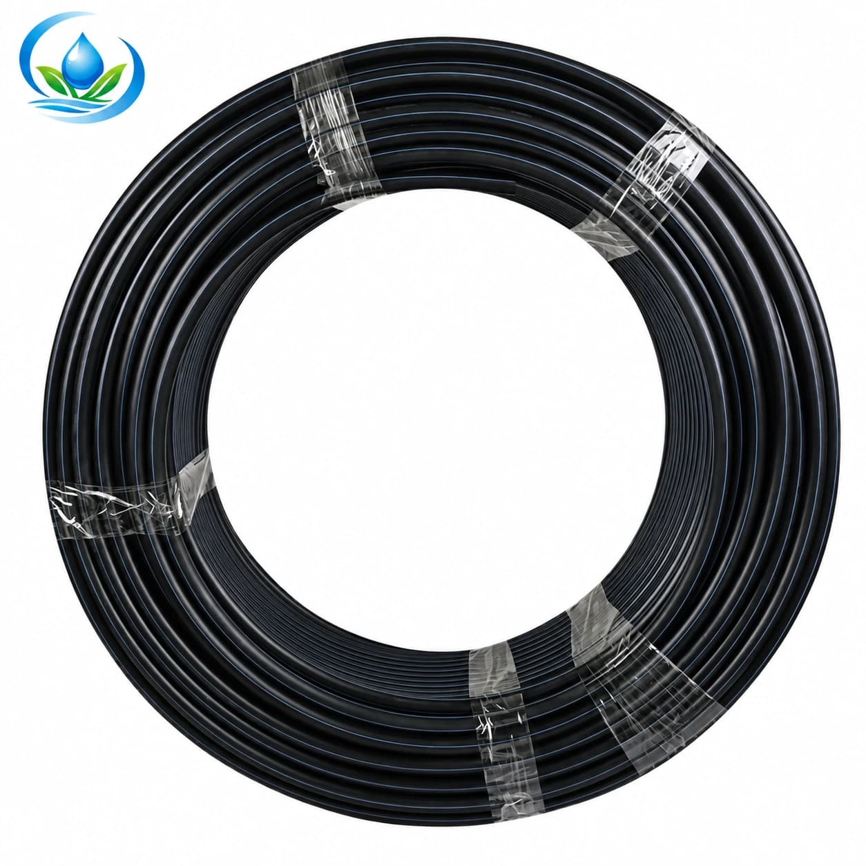
The published PE irrigation mainline pipe includes 32 mm outside-diameter options with different PE grade, PN, SDR and wall-thickness combinations. Its family also includes larger diameters. Choose an exact pipe option according to the designed flow, pressure envelope, route and joining method. Do not assume every 32 mm option shares the same internal diameter or pressure class. The agricultural pipe guide explains why grade, PN and SDR must travel together in a purchase specification.
Measure the actual pipe outside diameter at an undamaged, round section, and inspect its printed markings. A compression fitting grips and seals on the pipe geometry for which it is designed. Deep scratches, flattening or the wrong material can defeat a joint even when the nominal diameter is right. Confirm whether an insert, support sleeve or other part is required by the exact fitting and pipe manufacturer. Do not borrow an insertion depth or tightening method from another compression brand. Set aside enough pipe length to make a clean cut and provide strain relief without pulling the filter body sideways.
Support the filter and pipe as separate loads where the design requires it. The first PE section should not act as a lever on a plastic filter port when the line moves, expands or is stepped on. Leave a serviceable route around the filter body and a planned place to catch drainage when it is opened. Record the vertical or horizontal orientation specified for the filter option; do not rotate it merely to make the adaptor point toward an existing pipe. If the desired pipe alignment forces an inaccessible cover, revise the transition layout.
Build the physical chain with no hidden gaps
Write the chain left to right on the drawing: filter body and confirmed outlet → approved thread seal or mating surface → exact threaded adaptor → approved compression grip and seal → exact PE mainline option. Add required unions, isolation valves, pipe supports and gauges as separate items, in the locations selected by the designer. Each arrow means a verified mating interface, not an assumption that the preceding component looks the same size as the next.
A compression adaptor needs installation instructions for its exact design. Use the selected H-adaptor maker's procedure for pipe-end preparation, insertion depth, the supplied seal components and tightening. Check whether the chosen assembly calls for an insert, a particular cut preparation or a stated tightening method; those details cannot be inferred from the word compression. Keep the pipe straight and supported as specified so it does not pull the joint out of alignment. If the procedure is unavailable, obtain it before assembly rather than substituting steps from a similar-looking fitting. After installation, check the complete joint with water under the approved operating conditions.
Check whether a union is needed so the filter can be removed without spinning the mainline. A union is not included merely because the filter and adaptor appear in two product pages. If an isolation valve is proposed on either side, verify its pressure class and size and leave room to operate it. A drain should lead somewhere appropriate for captured water and debris. Every extra fitting affects physical length, pressure loss, cost and support, so include it in the drawing instead of discovering it after the pipe has been cut.
Check hydraulic and retail details before ordering
Compare the filter's exact maximum-flow label with the actual simultaneous demand of the zones downstream. The F32YD option's listed maximum of 6 m³/h is not a promise of low pressure loss at 6 m³/h or suitability for every source water. Request pressure-loss data for the selected body and element at the design flow. Compare filter, adaptor, pipe, valves and seals against the full pressure envelope; the lowest verified limit among the assembled parts matters. The filter's 8-bar maximum is not a target operating pressure for the farm.
Separate what is confirmed from what must be quoted. The Y-body disc filter and H-compression male adaptor have online ordering options, but the specific combination and all installation parts are not automatically included in those prices. Online ordering is not currently available for the PE mainline pipe; request current price, selling length and delivery for the exact grade, PN and SDR. Some adaptor options display no confirmed price; that is not a free offer. Ask the seller to itemize filter, adaptor, pipe, union, isolation and supports by exact code and quantity.
Send the connection schedule and photographs rather than the sentence “connect a one-inch filter to PE pipe.” Ask for the filter outlet's thread standard and gender, the H-adaptor's corresponding thread and seal, the specified PE OD and material, current model availability, and whether any insert or union is required. The PE branch-and-repair fittings guide covers other transitions along a field network; it cannot approve this filter joint from nominal labels alone.
Assemble and test one supported transition first
At the work site, isolate and depressurize the line using the approved procedure before opening the filter outlet or cutting the pipe. Compare the delivered model codes and actual mating ends with the written schedule. If the thread, seal face, compression size or pipe marking differs, stop and resolve it before assembly. Follow the exact product instructions for thread seal and compression tightening. Do not use excessive force to make a questionable pair appear watertight.
With the body properly supported and flow arrow correct, bring the system back into service under the manufacturer's approved procedure. Inspect the thread and compression interfaces at a named running condition. Record pressure before and after the clean filter and check for seepage after a suitable observation period. A dry initial joint is useful evidence but does not prove the connection will hold after pressure changes, service opening or pipe movement. Recheck in the normal operating zone and after the first planned service.
Keep the final chain with exact option codes, pipe grade/PN/SDR, thread identification, seal instruction, required supports, test pressure and date. The connection is ready to scale only when each interface is confirmed and a representative assembly performs as intended. Good irrigation pipe fittings choices make a filter removable and the mainline supported, while leaving the downstream pressure budget available to the crop.
Before you order
Compare this guide with the specifications for your exact product, selected option, water supply and field conditions. Your equipment requirements take priority over a general example.
Compare irrigation products