
Drip Tape Fittings: The Three Connections Every Replaceable Row Needs
Choose a compatible row start, repair join and serviceable end for a specific drip tape roll; test one row before ordering fittings for a whole vegetable block.
Published by IrriNex Store
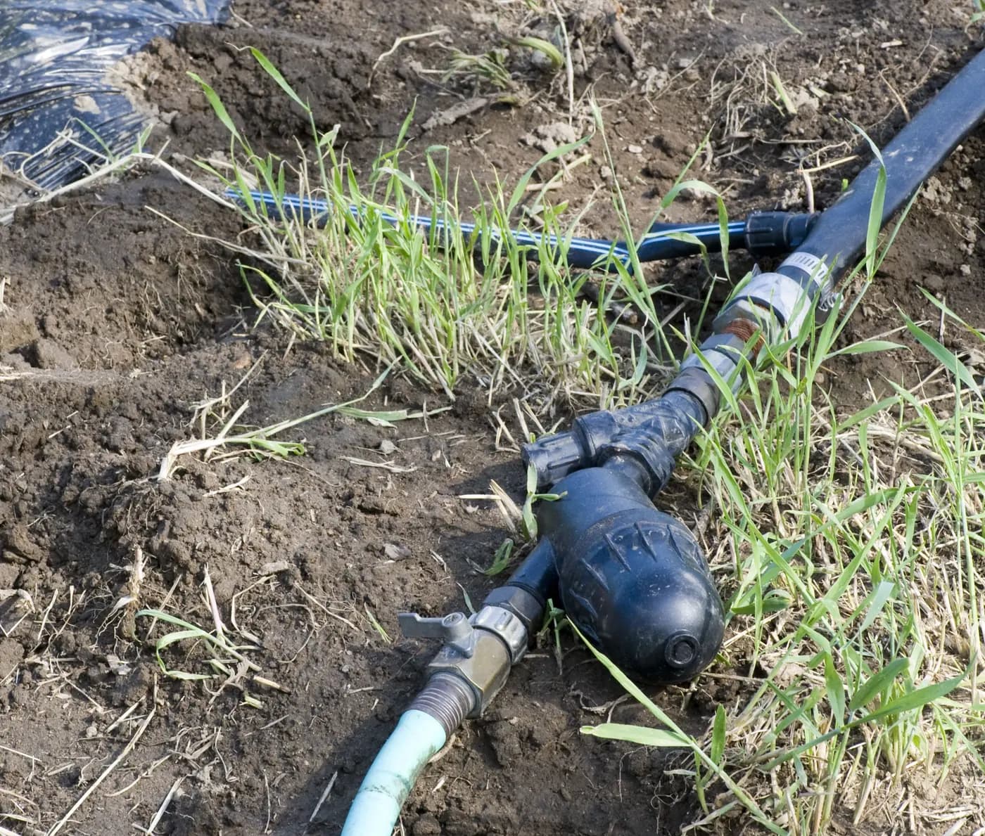
Drip tape fittings are easier to buy when you treat a crop row as three service points: a start at the header, a way to join sound tape after damage, and an end you can reopen for flushing. The same roll touches all three, but each point has a different mating surface and job. One nominal “16 mm” label cannot establish that a header takeoff, a tape-to-tape valve and an end cap are interchangeable. Before buying enough hardware for a block, select one exact tape option, draw one representative row, and prove how the three connections work together.
This guide is for a grower laying or renewing seasonal vegetable rows and wanting a repeatable repair plan. It is not a general irrigation system design or a claim that every fitting pictured in a catalogue suits every tape wall. If you are still choosing the overall water and filtration system, begin with the drip tape kit shopping guide. Here the outcome is a row card and a quantity list that make the first installation, an in-season cut-out, and a later flush practical.
Draw one row before counting fittings
Stand at the header and trace a representative lateral to its far end. Write down where the water leaves the header, what connection changes into thin-wall tape, whether a row valve is already present, where machinery or foot traffic can reach the line, and which end can be opened without sending discharge onto the crop or an electrical connection. Photograph the actual start from both sides. A collar at the tape end tells you little about the header side, which may use a punched opening, a gasket, a threaded adapter or another specified connection.
Give the row an identifier. Record its measured installed length, not the length printed on a sale roll. Mark any branches or centre feed because these create more than one far end. If adjacent rows use different old valves or headers, make a second row type rather than forcing a single fitting list onto the block. The general fittings guide separates barbs, locks and threads; this row card identifies which of those interfaces actually meets the selected tape at each service point.
A usable card has four columns: location, existing material and model, proposed exact part, and unresolved fit evidence. Add the person who checked the fit and the date of the first wet test. That small record prevents a later crew from using a visually similar fitting left in an unlabelled box. It also shows which spare should travel to the field when a row leaks during the crop cycle.
Choose the tape option before its connectors
Start with the actual flat-emitter drip tape option, not the family title alone. Store lists options with different nominal diameters, wall thicknesses, emitter spacings and roll lengths. A 16 mm option with a 0.15 mm wall and another 16 mm option with a 0.2 mm wall are not necessarily retained by the same collar. Neither wall thickness states the emitter discharge, maximum approved lateral length or pressure range for that exact configuration. Record the chosen option code and obtain its missing operating data before treating it as the design basis.
On the row card, copy the tape's nominal diameter, wall thickness, construction, and the manufacturer's permitted connector style. If the tape has a seam, check that the proposed connector is specifically intended to seal the selected tape construction. A connector that grips a smooth round dripline is not proven to seal a seamed, collapsible tape merely because both have a 16 mm trade size. Rivulis describes that distinction for its own connector families; it does not certify an unrelated Store combination. The tape label guide helps read wall and roll labels without treating a unit conversion as fit approval.
Keep a short, labelled offcut from the actual delivered roll for dry comparison, after confirming that the fitting maker allows that method. Do not stretch, heat or shave tape to make a collar close. If you cannot document an allowed wall range or installation method for the intended pair, buy a sample or obtain the two exact product instructions before multiplying a questionable connection over many rows.
Connection one: a start that matches both header and tape
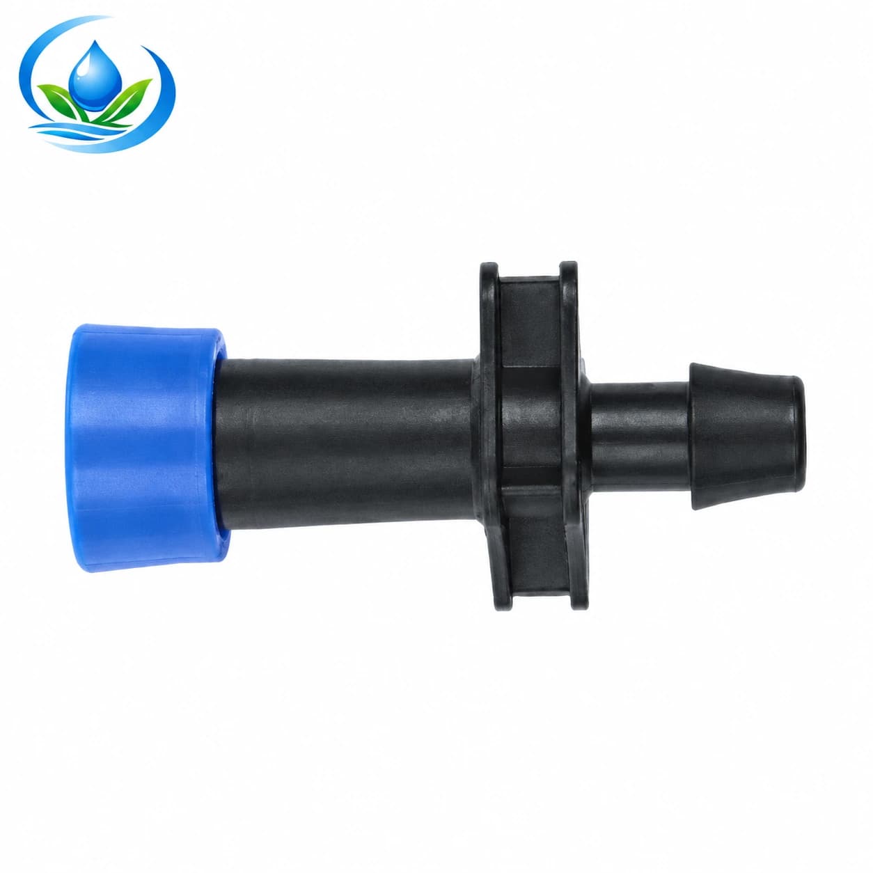
The row start has two different sides. Its upstream side must mate with the particular header wall, hole or outlet assembly; its downstream side must retain the tape. The lock-ring start offtake is a published nominal 16 mm product family. Its name does not establish the required hole punch, gasket, wall thickness, insertion depth or compatibility with every Store tape option. Match the exact catalogue part and header material with a documented mounting method before cutting a permanent header.
For a new header, mark row positions against the planting plan and leave enough working room to turn the collar and inspect it later. Support the header while making one clean test opening by the selected fitting's instructions. Remove cutting debris without pushing it inside. On a layflat header, a connector intended for rigid PE pipe cannot be assumed to work simply because the outlet nominal size matches. On rigid pipe, a connector intended only for layflat cannot be improvised with extra tape or sealant. Keep the header's pressure and wall specification alongside the fitting's approval.
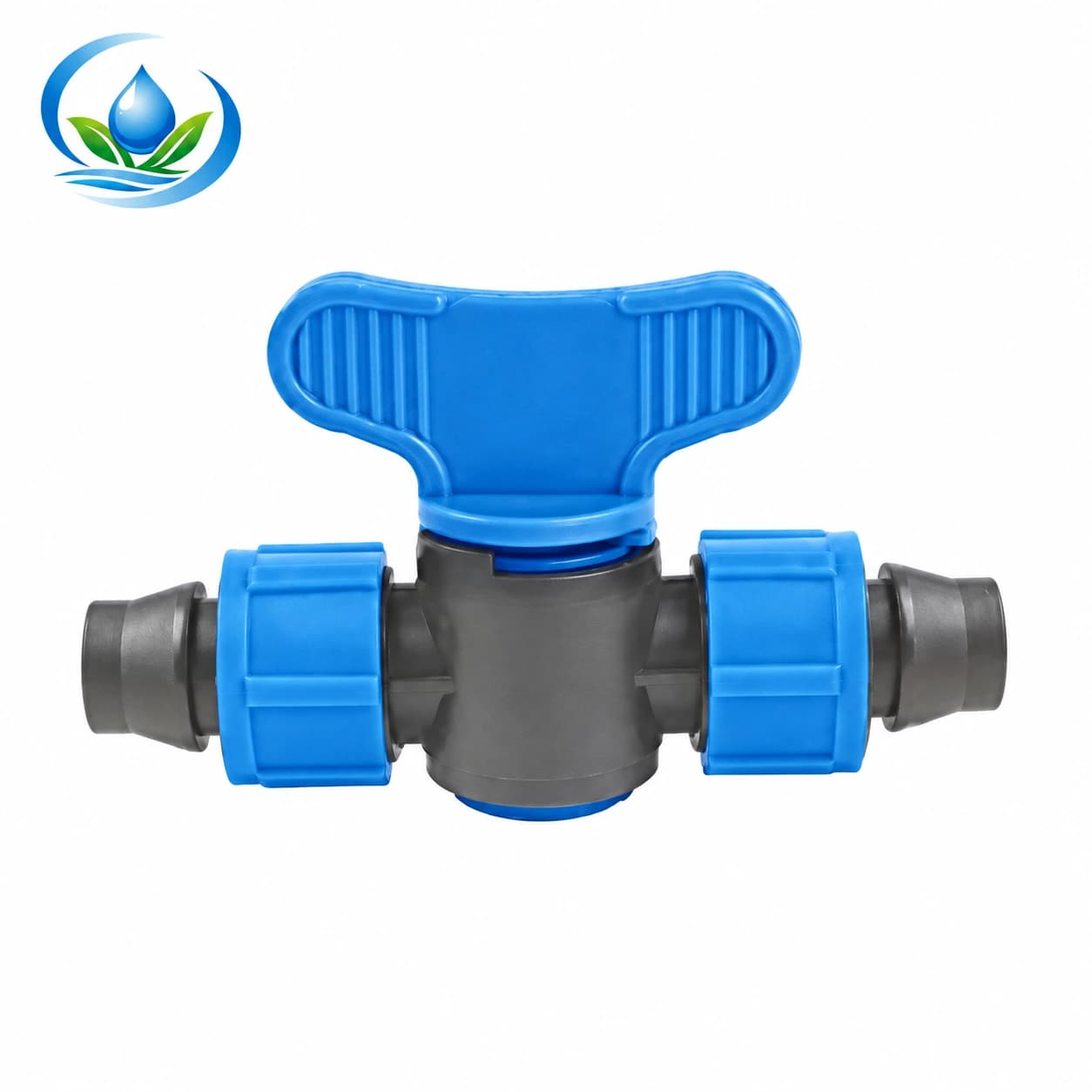
If a valve is needed at each row, identify where it belongs and what its two ends are. The published 16 × 16 mm tape coupler valve is a tape-to-tape interface; that makes it a possible inline service control where two permitted tape ends meet. It is not, from its label alone, a punched-header offtake. Some installations use a dedicated takeoff valve, others use a compatible takeoff followed by a separately supported valve. Draw the actual chain rather than treating every small blue-ring item as a substitute.
Connection two: a repair join planned before damage occurs
A repair join should connect two sound, square-cut tape ends of a permitted construction. Decide now what a crew will do if a wheel crushes a section, a rodent chews it or a temporary installation folds sharply. A pinhole may require a different part than a torn seam. A long tear is not a reason to wrap the tape tightly and hope the far emitters still work. Isolate and depressurize the row, remove the damaged length to sound material, keep plastic chips out, and follow the selected coupler's insertion and locking instructions. Retest under ordinary zone operation.
The hole-repair and end-closure guide distinguishes a puncture in the wall from an open line end. For a cut-out, count the resulting joints: one simple tape-to-tape coupler closes a single cut, while replacing a damaged length with a sound patch normally creates a join at each side. If a valve is used as the inline join, confirm its permitted tape wall on both sockets and locate it where the operator can reach it without stepping on wet beds. A closed valve changes the downstream irrigation; mark it visibly so it is reopened before the next planned run.
Carry one correctly labelled repair sample for each tape-and-fitting combination used in the block. Do not replace a damaged tape section with a different nominally similar roll left from another zone unless its hydraulic characteristics and fit have both been checked. A patch can seal mechanically yet deliver a different amount of water. Record the patch length and location so an unusual wetting pattern can be investigated without guessing which row was changed.
Connection three: an end that can be opened and closed again
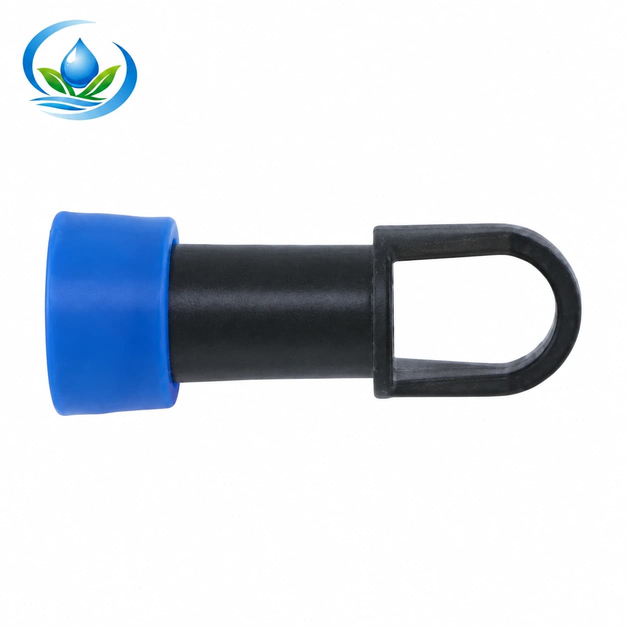
Every independent far end needs a closure appropriate for the selected thin-wall tape. The published lock-ring drip tape end cap with pull loop is a nominal 16 mm item, but a safe selection still requires its permitted tape construction, wall range and closure method. A barbed plug for thick-walled round tubing or a tiny punched-hole plug is not a substitute. Compare the actual end of the selected roll to the cap instructions. Do not force the ring over a twisted or dirt-filled tape end.
Place the end where it can be found and opened for flushing without uprooting plants or contaminating harvested produce. Allow enough slack for normal contraction and service, while protecting the line from wind, field traffic and tools. A tightly pulled end may leak after the first temperature change or when the operator lifts it to flush. If the selected design uses a different flush valve, confirm its inlet and operation rather than assuming the word “flush” means it opens automatically.
Penn State Extension describes periodic mainline, header and drip-tape flushing as part of vegetable-system maintenance in its vegetable drip irrigation guide. A removable closure gives a practical outlet for that job, but the number of ends opened at once and the flushing method must follow the system design. Direct discharge to a safe place, inspect what leaves the line and close the exact end securely before checking the row again at working pressure. The Store's lateral flushing guide covers the recurring maintenance task after installation.
Run a one-row fit test before ordering the whole block
A dry hand fit can reveal an obvious mismatch, but it cannot prove sealing or retention during a full irrigation cycle. Choose a row that represents the common header, tape option and pressure conditions. Assemble one approved start, one planned inline repair fitting on a sample or appropriate segment, and one end. Label the models and tape code. Flush the upstream line as instructed before closing delicate tape connections, then bring the zone into operation by the farm's normal procedure. Do not use compressed air or exceed the documented pressure to “prove” strength.
Observe the start first: any seepage around a header hole, gasket or tape seat, any movement at the collar, and any restriction caused by a partly inserted fitting. At the sample join, inspect both sides and operate the valve if one is part of the plan. At the far end, inspect the closure and water delivery from nearby emitters. Stop and depressurize before correcting a leak. If a joint slips, recheck permitted tape wall, insertion depth and damaged pieces; an extra unapproved clamp is not a compatibility solution.
Repeat inspection after a normal shutdown and restart. Retained old collars may behave differently from new ones, and pressure transients can expose a marginal connection. One successful test supports only that exact combination under the observed conditions. If the block has a second header material, tape wall or row valve model, run a separate representative test. The new roll and retained valve guide addresses the narrower decision to reuse existing start valves.
Convert the row map into quantities and labelled spares
Count physical starts, planned service joins and independent far ends separately. For example, a straight block with 24 one-direction rows has 24 start points and 24 end points, but its initial number of inline repair couplers may be zero. A centre-fed arrangement with two lateral arms per crop row changes the count. Do not add a valve at every hypothetical damage location. Instead, choose a clearly labelled service reserve based on how quickly parts can reach the field, how often the tape is handled and whether multiple tape types are installed.
List fitting quantities by exact product code and connection, not by colour or “16 mm plastic fitting.” The start-offtake count must include the correct header-side sealing pieces, if sold separately. The repair reserve must match the selected tape wall. The far-end count must preserve access for flushing. Add a suitable punch or cutting tool only after the required opening and material are confirmed; an oversized opening can make an otherwise correct takeoff leak. Compare selling unit, current availability and delivery on each actual product page. A zero or missing listed price is not evidence of a free item.
Keep tape offcuts, photos of assembled examples and an annotated row card with the spare box. When a crew removes a cap for flushing or replaces a broken length, it can identify the matching replacement without guessing from the outside shape. Review the count after the first representative installation, when hidden bends, header repairs or access constraints become visible. Order the remaining block only after the three service points and any needed second row type have passed the same checks.
Use the three-connection decision when a row fails
A leak near the header is not automatically a tape problem. Inspect the upstream seal, header hole, connector body and tape seat separately after safe shutdown. A wet patch in the middle of the row may be a puncture, failed patch, cracked coupler or pressure-related split. A wet far end may be a dirty seat or an end cap that does not match the tape wall. Fix the cause that the evidence identifies; replacing an entire roll because a gasket failed wastes both material and installation time.
When the same fitting fails on several rows, pause further installation. Compare their lot, tape option, pressure observations and assembly procedure. A single bad part can be replaced; repeated slippage across a block points to an interface or operating mismatch that a larger bag of the same fittings will not solve. If damage follows machinery traffic, move or protect the line instead of treating connectors as disposable. If far-end debris recurs, check filtration and the approved flushing routine before blaming the cap.
The final purchase decision is therefore concrete: one documented tape option; one start whose two interfaces are approved; a repair join that handles the actual tape construction; and an end closure that can be serviced. Keep the row card with the ordered codes and the wet-test result. That is enough to install, repair and reopen a representative row without relying on nominal diameter or appearance as proof of fit.
Before you order
Compare this guide with the specifications for your exact product, selected option, water supply and field conditions. Your equipment requirements take priority over a general example.
Compare irrigation products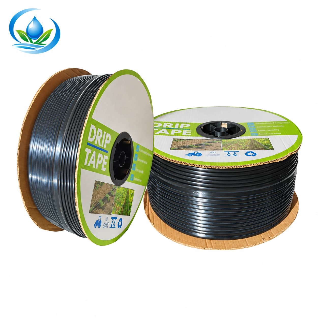
.jpg)