Lateral Irrigation Line Flushing: Plan End Access and Check the Discharge
Map the crop lateral and its accessible end, plan approved water discharge, observe debris, restore the matched closure and check emitter delivery afterward.
Published by IrriNex Store
A lateral irrigation line can carry loose material toward its crop-row end even while the upstream filter is working. For an in-season water flush, the useful plan identifies the actual lateral, a reachable approved outlet, the row groups allowed to run, and a place where discharge can be observed without damaging the crop or its surroundings. Open or refit an end only after the affected supply is isolated and pressure is released by the installed system's procedure. During the controlled run, record what comes out; afterward, close the matched end and check delivery under normal operation. Lateral irrigation line flushing access should be mapped from the upstream route to the identified end closure.
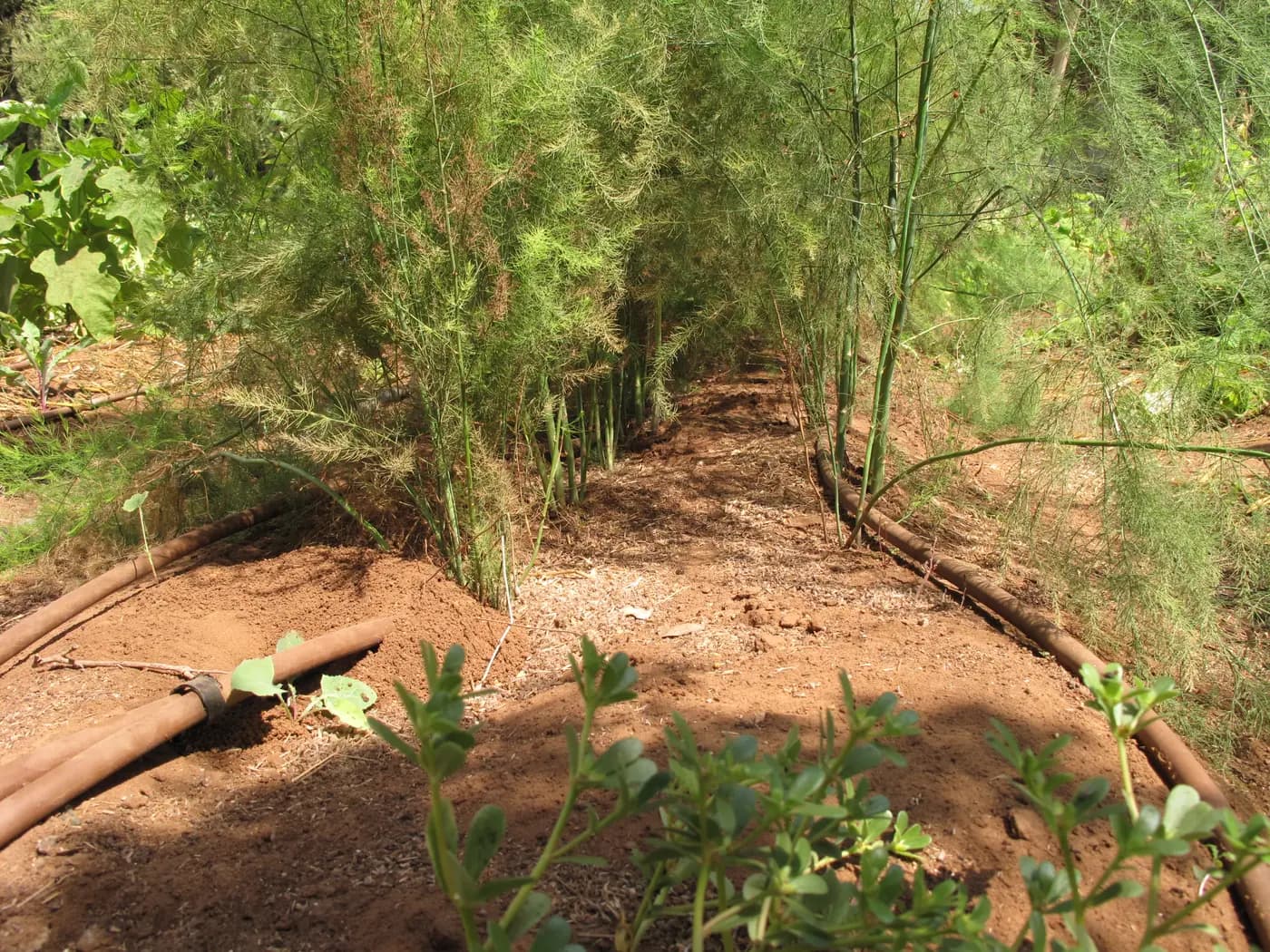
This approach helps a grower who can still reach the end of a planted row but needs to know which line was flushed, where the water went and whether the closure was restored correctly. The opening photograph shows drip laterals beside asparagus and an access path; it does not show flushing or identify a Store fitting. A clear-looking discharge is useful evidence about the water leaving that outlet at that time. It does not demonstrate that every emitter passage is open again.
Which pipe is the actual crop lateral that needs access?
Begin at the crop-row end and trace the tube back to its takeoff from the header or submain. Mark the row number, lateral material, approximate route, end position and valve that actually supplies it. Do not call a shared header the lateral merely because both are black pipe. Sediment held upstream may enter the row again after an end is closed, so the installed design's prescribed order of header and lateral work matters. Follow that design or obtain a hydraulic service plan rather than inventing a universal valve sequence.
Inspect the growing crop around the endpoint before choosing a work path. Can a person reach the end without stepping on tubing, disturbing stems, pulling a trellis line or crossing a wet harvest lane? Can a discharge hose or other approved outlet be supported so the line is not loaded by its weight? Mark the approach on a field sketch while the row is visible; late canopy growth can hide the end and turn a simple service point into a crop-damage problem. A practical plan gives the operator room to see both the line and the discharge route.
If one manifold feeds several rows, identify each row end independently. A flow measured at the shared header does not reveal which lateral was actually opened. Label similar caps or valves on the map by row and connection type. This also helps reconcile the closure count when a line is split, looped or centre-fed. The end-closure selection guide explains how a full-bore row end differs from a punched emitter-hole repair. Here, the map is a service route and result record, not merely a parts count.
Does the observed symptom justify a water flush before replacement?
Record the symptom before changing the system. Is there loose grit at an accessible end, a recurring weak far row, an unexplained change after upstream pipe work, or material found during an earlier approved flush? Photograph the source-side condition and a representative near and far outlet if the symptom is uneven delivery. A weak emitter may also reflect a kink, pressure loss, wrong valve state, a leaking joint, an obstructed emitter path or a filter issue. A flush can remove some mobile material from a pipe; it cannot prove or repair all of those causes.
Check the installed filter's condition and any available pressure/flow record under a comparable operating case. If particles are seen beyond a screen-filter housing, the screen-filter service guide helps distinguish loading from a torn element, seal bypass or downstream introduction. If a disc filter has just been serviced, use the disc-stack return-to-service checklist to verify its own reassembly and running readings. Neither filter task is replaced by opening a crop-row end, and an end flush cannot make an unprotected supply acceptable for emitters.
Before choosing the work, ask whether fertilizer, disinfectant or another input recently passed through the line. Follow its label, the site's water handling rules and the equipment maker's instructions for any residual solution. A general water-flushing article does not authorize chemical treatment or disposal into a canal, ditch, water source or crop area. Where the liquid's identity is uncertain, pause and identify it before routing discharge.
Make a named group and a safe discharge route
Write a short group sheet with the supplying valve, rows included, intended outlet points, available source condition, and who will control the start and stop. Some systems can serve only a limited flushing arrangement while retaining the operating condition the maker requires. Opening every end together may leave too little flow in each lateral; opening an arbitrary one at a time may also depart from the specified procedure. Use the actual line and headworks documentation or a qualified hydraulic review to select the group. There is no transferable number of ends, flush velocity, pressure, duration or calendar frequency for all farms.
For each outlet, decide where water and entrained solids will go. The route should remain visible, secured and compatible with the installed system's approved discharge method. Keep flow away from electrical equipment, pump foundations, unstable soil, traffic and harvest handling areas. Do not let a hose whip, undermine a riser or pull a tube off its header. If the outlet is below the crop canopy, plan enough space to observe it without kneeling in a jet or reaching across moving pipe. Use barriers or a second person when the site's normal operating rules require them.
Set up a simple observation record before starting: group ID, row ID, end location, source/valve condition, whether any permitted other zones are running, visible debris at the beginning and later in the same run, and any leak or change in delivery. A transparent collection vessel or receiving area may help observation if approved for that discharge. It is not a laboratory particle count. Keep photographs or notes tied to the row rather than a bag of unlabeled sediment. The record makes a repeated dirty end distinguishable from a one-time construction particle.
Isolate and depressurize before changing an end
Do not twist or pull a cap from a live lateral. The fact that a nearby emitter has stopped dripping does not prove that the end is depressurized; trapped pressure, an elevated tank or an automatic start may still be present. Identify the correct supply isolation, controller or pump stop, and pressure-release points from the installed equipment instructions. Prevent unexpected restart while the end is being handled. Confirm the pressure state by the method the equipment maker specifies before removing or refitting a closure.
Inspect the accessible end after isolation. Look for a split, stretched tube, distorted fitting, damaged lock, soil packed into the opening, or a previous improvised tie that may fail when water returns. Photograph the original connection before disturbing it. If the cap or tube is damaged, record the exact material and dimensions for a replacement decision; do not force the old piece back solely to finish the task. Avoid cutting or reaming a service outlet unless the specific product instructions require it. Keep the open end and replacement parts clean while the discharge route is prepared.
Once an approved outlet arrangement is secured and people are clear, restore water only through the installed model's permitted flushing sequence. Observe from a safe position as flow begins and stabilizes. If a connection moves, an outlet route fails, pressure goes outside the permitted operating condition, or erosion starts, stop by the designated control. Do not raise pump speed or bypass pressure protection to make a weak flush look stronger. Do not substitute compressed air for the water procedure described here.
Observe the discharge without inventing a universal stopping rule
Write down what is actually visible: coarse grit, fine suspended material, plant fragments, colour change, intermittent debris, or no visible material. Note whether the observation was at first arrival or after stable flow. A short first pulse after a pipe repair can mean something different from material that recurs every time the same row is opened. If the water appears clearer later, record that change and the operating condition. Do not turn “clear to the eye” into proof of microscopic cleanliness or restored dripper flow.
Use the equipment supplier's approved performance criterion and the installation's available supply to decide how the run should be conducted and when it should end. The producer of another dripline may discuss keeping enough flow available for flushing, but its value and sequence do not automatically apply to this lateral. A fixed number of minutes, a generic pipe velocity or a command to open a set number of row ends would ignore length, diameter, slope, emitter demand and source behaviour. Keep observations specific enough that a technician can later judge whether further work is needed.
If discharge remains unexpectedly dirty, varies sharply between adjacent rows or weakens while the outlet is open, note the condition and investigate the upstream route, filter, valve state and hydraulic supply. Repeating the same uncontrolled flush is not a diagnosis. A clean-looking end flow with a dry crop section can point toward blocked or damaged emitters, a folded line or inadequate operating pressure. The visible material and the plant delivery must be assessed separately.
Restore the exact closure and inspect it under normal operation
After the approved flush, stop the affected supply and release pressure by the specified method again before touching the outlet or replacing a cap. Check the cut end for damage and contamination. Refit only a closure confirmed for that line's actual material, mating diameter, wall or bore, retention system and pressure condition. A nominal “16 mm” description alone cannot prove a lock-ring part, barbed cap or dripline will seal together. Do not seal a required vent or bypass port with a spare end cap merely because it seems to fit.
Run the group in its usual irrigation arrangement after the endpoint is secured. Watch the closure and neighboring connections for leaks or movement, check the permitted operating pressure at useful points, and compare representative near and far emitter delivery under comparable collection conditions. Water leaving an open end can look clear while an individual emitter remains obstructed. If delivery does not return to the accepted baseline, keep that row marked for diagnosis rather than closing the record as “fixed.” Recheck an adjacent row if handling disturbed its shared header or fittings.
The zone restart guide explains broader acceptance after a seasonal shutdown; its inlet-to-row checks can help when several components were disturbed here. In-season lateral flushing has a narrower record: which rows were opened, how discharge changed, which closures were restored, and what normal operating delivery was observed afterward. For pressure measurements, use the drip pressure checklist to name the measurement points rather than relying on a static headworks gauge alone.
Compare current line and end products by connection, not appearance
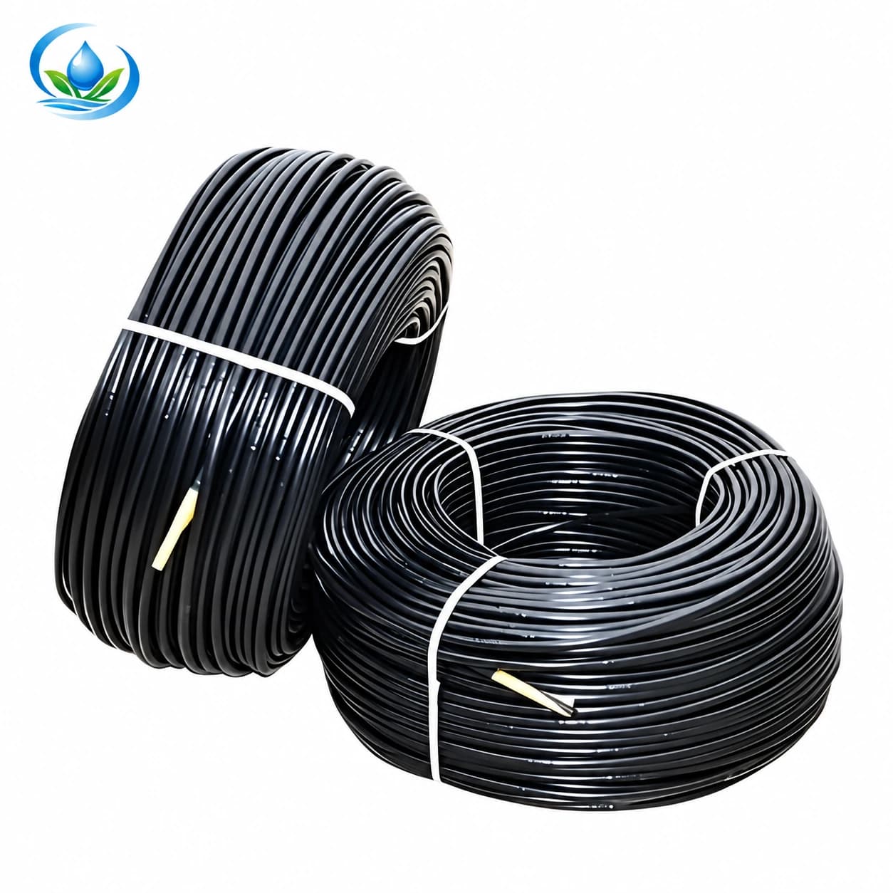
The published IrriNex inline drip pipe is a family of round crop-row laterals with built-in emitters. One current option has code IS-3-8CDA6B18CD. That option has a nominal 16 mm diameter and a 0.8 mm wall. Its integral outlets are 30 cm apart and listed at 2 L/h each; the sale roll contains 500 m. Those entries describe that offered line, not the flow required to flush it or a permitted maximum installed lateral length. Record the actual line code and an undamaged sample before asking for a replacement length. A pipe sold under the same nominal diameter may have another wall, bore or emitter arrangement.
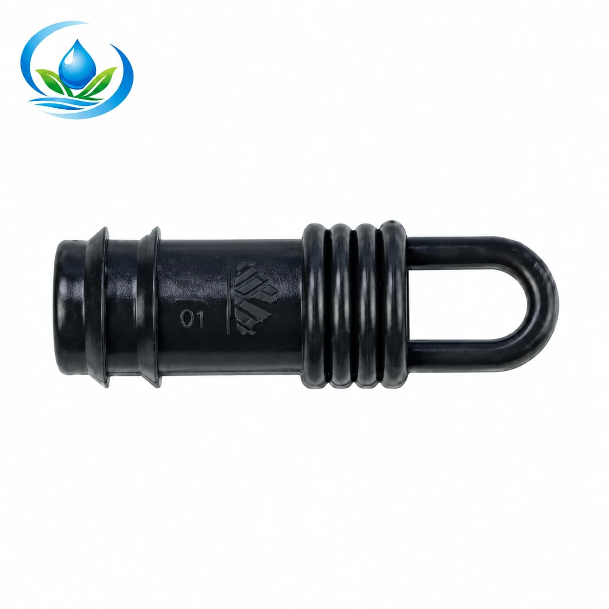
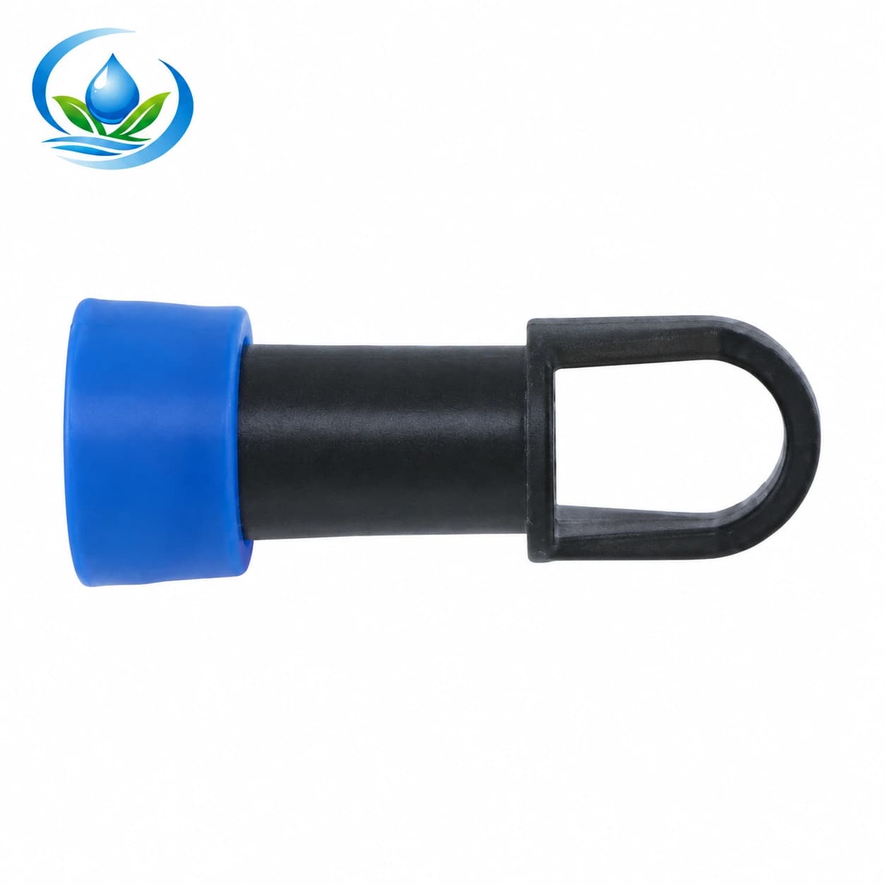
The published barbed end-cap family lists EL0116, EL0120, EL0125 and EL0132 for nominal 16, 20, 25 and 32 mm options. The catalogue shows these as barbed full-bore closures, not automatic flushing valves. The LE027 lock-ring end cap is a separately listed nominal 16 mm geometry. Its catalogue family and size do not prove it grips the installed inline pipe, thin-wall tape or a damaged end. Ask the supplier to verify the exact pipe/fitting combination and any required retention or installation method. If that match cannot be established, do not substitute a visually similar closure in the field.
Count replacement pieces only after mapping actual outlets and failed parts. An end that remains sound and compatible may be refitted according to its instructions; a cracked body, missing retainer or split tube may need a different repair. Select the matching option on its product page, then check the current price, pack quantity, availability and delivery for that option. If the tube-to-fitting match is still uncertain, ask support to confirm it before buying; a shared “16 mm” label is insufficient. None of these end caps opens automatically for flushing; any dedicated flush valve must have its own documented operation and verified line connection.
Close the field record and plan the next visit
| Record field | Useful entry | Decision it supports |
|---|---|---|
| Row and group identity | Named valve, actual lateral and accessible end | Repeat the same route without guessing |
| Discharge arrangement | Approved outlet path and observed material | Keep water and solids controlled |
| Operating context | Source state, other open groups and pressure/flow readings if available | Compare later observations fairly |
| Restored closure | Product and size, actual line identity, leak check | Confirm that the end was returned to service |
| Emitter check | Representative near/far delivery after closure | Separate pipe flushing from emitter recovery |
| Unresolved finding | Location, symptom and responsible follow-up | Avoid an unsupported “all clear” |
Give the next operator a route map and the reason to revisit each marked end. A recurring dirty discharge may justify investigation of source water, filter integrity, header debris or recent pipe work. A leak after every refit may point to the wrong mating geometry or a damaged tube end. In either case, repeating the observed row and condition is more informative than applying a universal weekly flushing schedule.
Keep the winter parts inventory for the separate end-of-season task: drainage, identification and storage. During the growing season, leave the endpoint reachable and protected according to the crop and equipment instructions, and document any field work that later blocks access. The completed flush record states what water was routed, what material was seen, what closure was fitted and whether normal delivery was actually checked. Those observations make the next maintenance or buying decision specific to this lateral.
Before you order
Compare this guide with the specifications for your exact product, selected option, water supply and field conditions. Your equipment requirements take priority over a general example.
Compare irrigation products