
Drip Irrigation Pressure Regulators: Sizing, Placement, and Troubleshooting
Choose a drip pressure regulator from measured inlet pressure, zone flow, outlet target and connection standard, then install and test it under real operating conditions.
Published by IrriNex Store
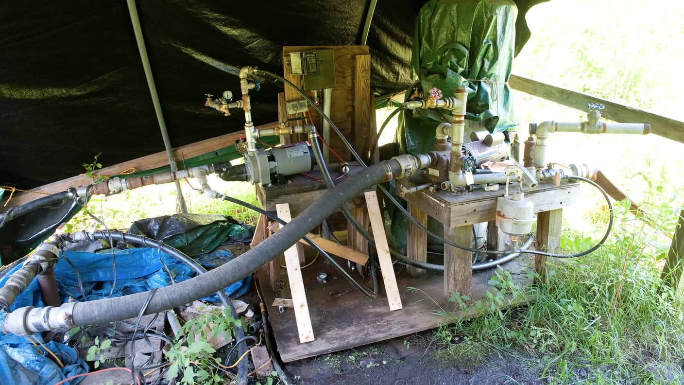
A drip irrigation pressure regulator should be selected from measured dynamic inlet pressure, total zone flow, the outlet pressure required by the lateral, the connection standard and the regulator's permitted duty. Matching only the printed PSI value can produce a part that fits the pipe but never reaches regulation, restricts a large zone, or remains under static pressure when it is designed for flowing service. This guide explains how a regulator behaves, how to compare fixed and adjustable models, where to place it, how it differs from a pressure-compensating emitter, and how to diagnose an outlet reading that is higher or lower than expected. It is written for agricultural drip tape, inline dripline, greenhouse and orchard zones.
Understand what the regulator can and cannot control
A pressure regulator is a valve that reduces a sufficiently high inlet pressure toward a stated downstream pressure while water flows within its operating range. It does not increase low pressure. It also consumes some pressure as water passes through it. The supply therefore needs enough dynamic pressure to cover the desired outlet setting, the regulator's own loss and the remaining losses in pipe, filter, valves and elevation.
A fixed regulator has a preset nominal outlet. An adjustable regulator allows a range to be set, but it still has inlet, flow and installation limits. A pressure-limiting valve or a regulator rated for continuous static duty is a different selection from a small flow-through unit that belongs downstream of a zone valve. Use the manufacturer's technical sheet to identify the duty rather than judging from body shape.
Regulation is one part of uniformity. An undersized mainline, clogged filter, excessively long lateral or steep field can still create large differences after a regulator. The farm drip irrigation system design guide shows how to build the complete pressure budget.
Five inputs for sizing a drip irrigation pressure regulator
A drip irrigation pressure regulator sizing check should pair each candidate's flow envelope with the actual pressure measured upstream while that zone is running. Write down the following values for each independently operated zone:
- Dynamic inlet pressure: pressure at the proposed regulator location while the intended zone flow is moving.
- Minimum and maximum zone flow: demand when the smallest and largest planned groups operate, including future stages only when they are part of the actual design.
- Required downstream pressure: the pressure needed at the regulator outlet so the farthest lateral remains within its specified operating range.
- Connection: actual pipe or thread standard, inlet and outlet size, male or female form, and required adapters.
- Duty and placement: whether the device will be isolated by a valve, left under static pressure, installed outdoors, or exposed to fertilizer solution.
Record the units beside every number. PSI, bar, kilopascals, litres per hour, litres per minute, gallons per hour and gallons per minute are easy to confuse. Convert once on the worksheet and retain the original product values for checking.
Calculate the complete zone flow
A regulator works correctly only within a stated flow range. Calculate the water passing through it, not the maximum capacity of the source. Multiply the outlet flow of the exact lateral option by the number of outlets or metres operating together. Add separate branches that are supplied through the same regulator.
Consider both ends of the range. A large fixed regulator may serve the full zone but fail to regulate when only one short sub-zone is open. A small unit may operate correctly for a trial row yet create excessive loss when every row runs. If several zones operate separately, each downstream regulator should be checked against the flow of its own zone.
For agricultural tape, use the exact spacing and discharge option on the selected agricultural drip tape page. For reusable tube, use the selected inline dripline variant. Do not calculate from roll length alone; only the length running simultaneously contributes to regulator flow.
Set outlet pressure from the lateral requirement
The correct setpoint is not a universal number. Begin with the working-pressure range of the selected tape, tube, emitter and fittings. Then use the hydraulic calculation to determine what pressure must leave the regulator so the start and far end remain acceptable. Long rows, friction and uphill elevation may require more pressure at the zone inlet than at the last outlet, but never exceed the weakest component's limit.
Thin-wall tape often has a lower permissible pressure than robust inline dripline. Even two products in the same family can differ by wall thickness, emitter construction or connection. Read the exact variant sheet. If no supported pressure range is available, obtain it before choosing a preset regulator.
The IrriNex catalogue lists the PRO134 regulator in preset 15, 20, 25 and 30 PSI options with a listed 3/4-inch female × 3/4-inch male connection. Treat those as options to compare, not as a recommendation for every field. Confirm the selected option, inlet limits, flow range and thread standard before ordering.
Check regulator inlet margin at the planned zone flow
A regulator can hold its stated outlet only when the inlet pressure is sufficiently higher. The difference must cover internal valve loss while the target flow moves. If the inlet falls near or below the required threshold, the device becomes a restriction and outlet pressure follows the weakening supply instead of remaining at the preset value.
Utah State University Extension explains that a pressure-regulating valve discharges its set pressure only when inlet pressure is greater than the setting plus valve losses. Its irrigation-uniformity guidance also notes that regulators add loss and that economics should inform whether control is placed at a manifold, lateral or individual outlet.
Measure during the worst credible supply condition. A clean-filter test made with a full tank may conceal the low pressure that appears with a dirty filter, a low reservoir or another zone sharing the pump. Do not compensate by choosing a lower regulator setting until the crop and lateral requirements have been checked.
Match threads, direction and service duty
Confirm the inlet and outlet independently. Similar-looking 3/4-inch threads may follow BSP, NPT or hose standards and may use different sealing surfaces. Record male or female orientation and identify every adapter. Avoid building a long unsupported chain of fittings around a light plastic body.
Install in the marked flow direction. A backward regulator may leak, restrict flow or give an unstable reading. Keep it accessible and provide enough straight, supported pipe for removal. Protect the assembly from vehicle traffic, freezing conditions and direct mechanical load.
Determine whether the selected model tolerates continuous upstream pressure with no downstream flow. Many small irrigation regulators are intended to sit after the control valve so they are pressurised only when the zone runs. A model specifically rated for static or continuous duty may be used elsewhere according to its instructions. Never infer this rating from the preset pressure alone.
Place the regulator with the valve and filter in mind
A common zone arrangement is source protection, control valve, filter and regulator, followed by the main or lateral distribution. The final order depends on equipment ratings, backflow rules, filter design, fertigation and whether the filter must remain under constant pressure. Follow the applicable manuals and local requirements.
Placing the regulator after the filter protects its small internal passages. Installing it downstream of a normal on/off valve also avoids static duty when the model is designed for flowing service. On a farm with a high-pressure mainline and multiple low-pressure zones, each zone may need its own regulator so different demands and setpoints are handled independently.
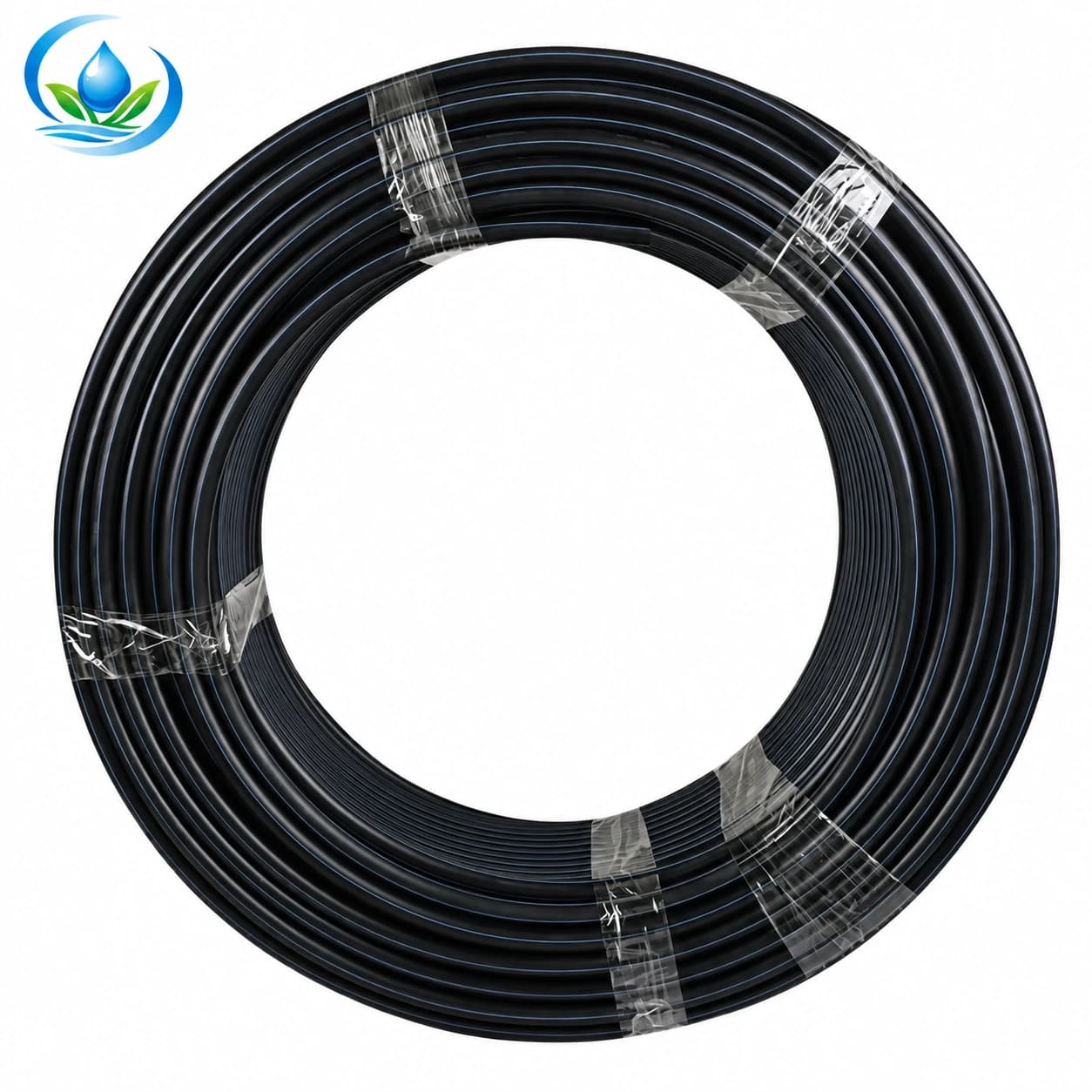
The delivery route still needs correct sizing. Review the published PE irrigation mainline options and calculate friction at actual zone flow. A regulator installed far upstream cannot remove pressure variation created by an undersized downstream pipe.
Do not confuse regulation with pressure compensation
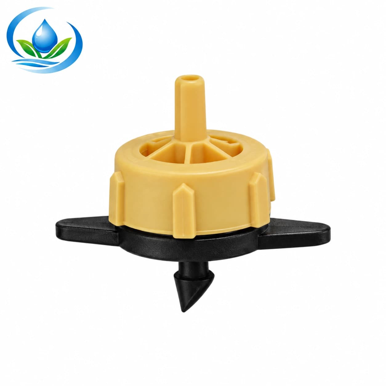
A line regulator controls downstream line pressure within its operating limits. A pressure-compensating emitter uses a small flexible element to keep the individual outlet flow comparatively stable over a specified inlet range. It does not lower the pressure carried by the pipe for every fitting and component.
A pressure-compensating emitter can help manage moderate differences among plant positions, especially along slopes or long orchard laterals. It still requires suitable inlet pressure, filtration and pipe design. If the pipe or fittings receive pressure above their rating, pressure compensation at the emitter does not protect them.
Some projects use both: a zone regulator protects and sets the lateral pressure, while compensating emitters improve individual discharge uniformity within their specified range. Compare the cost and maintenance of regulation at the zone, submain, lateral or outlet against the field's measured pressure variation.
Commission the regulator with two gauges
Flush new pipe and clean the filter before assessing regulation. Install or temporarily connect a gauge upstream and downstream of the regulator. Open the intended zone, allow air to leave, and wait for stable flow. Record inlet pressure, outlet pressure and total flow at the same moment.
Repeat with the smallest and largest legitimate zone configuration. Measure downstream pressure near the far lateral as well as near the head assembly. This distinguishes a regulator issue from mainline or lateral friction. Where an adjustable regulator is used, follow the stated adjustment procedure and never exceed component limits while tuning.
Keep these readings as the clean baseline. Later, a falling pressure after the filter may indicate clogging; a normal regulator outlet with a low far-end reading points toward distribution loss; an outlet that rises above the setting may indicate inadequate flow, incorrect placement, internal wear or the wrong device type.
Troubleshoot from measurements, not symptoms alone
| Observation | Checks | Likely direction |
|---|---|---|
| Outlet pressure is too low | Measure inlet pressure and zone flow; inspect filter and upstream valve | Insufficient inlet margin, excessive flow, blockage or undersized delivery pipe |
| Outlet pressure is too high | Confirm flow is above the minimum; check direction, duty and gauge accuracy | Too little flow, wrong model, incorrect installation or internal wear |
| Pressure oscillates | Observe pump cycling, valve movement, trapped air and changing zone demand | Unstable source or regulator operating outside its range |
| Near rows work, far rows do not | Compare pressure before regulator, after regulator and at far laterals | Distribution friction, elevation, excessive lateral length or clogging |
| Fittings open at startup | Check static duty, opening sequence, transient pressure and component ratings | Surge, excessive setpoint, wrong fittings or missing restraint |
Use a gauge with a useful scale around the expected values. A very high-range gauge can hide small but important changes in a low-pressure drip zone. Confirm gauge accuracy before replacing the regulator.
Use a pre-order regulator checklist
- Selected lateral variant and documented operating-pressure range.
- Calculated minimum and maximum flow through this regulator.
- Measured dynamic inlet pressure at those flow conditions.
- Desired outlet pressure and required inlet differential.
- Maximum inlet and body pressure rating.
- Flowing, static or continuous duty rating.
- Inlet and outlet size, thread standard, gender and flow direction.
- Position relative to valve, filter, fertigation equipment and test points.
- Service clearance, support, weather protection and replacement plan.
Use the field-ready component shopping list to check the rest of the head assembly. If a data sheet is unclear, send the worksheet and product links through IrriNex Store support before ordering. A useful question includes flow, dynamic pressure, setpoint and thread measurements.
Frequently asked regulator questions
Can a regulator raise low pressure?
No. It reduces a higher inlet toward a lower controlled outlet and adds its own loss. A weak source or excessive pipe loss requires a supply or hydraulic correction.
Does every zone need a separate regulator?
Not always. Separately operated zones with different flows or pressure targets often need independent control. A designer may use a central regulating valve when its range and downstream hydraulics support all operating cases.
Is a 25 PSI regulator correct for all dripline?
No. The setpoint must follow the exact tape, dripline, emitter and fitting ratings plus the zone pressure budget. Thin-wall tape can require a different pressure from robust tubing.
Why is outlet pressure above the label?
Check whether enough water is flowing, whether the model is installed in the correct direction and duty, and whether the gauges are accurate. Some flow-through regulators do not control static pressure.
Where should pressure be measured?
Measure immediately before and after the regulator while the zone runs, then also check representative lateral starts and far ends. The readings separate source, regulator and distribution problems.
Select by operating envelope and verify in the field
The printed outlet pressure is only one line of the decision. A dependable selection matches zone flow, dynamic inlet pressure, required differential, component limits, threads, direction, placement and service duty. The regulator then needs commissioning at the smallest and largest intended flow.
Keep the measured baseline with the system record. When performance changes, compare inlet, outlet and far-end readings before adjusting or replacing parts. That measured approach protects drip tape and fittings, supports more even delivery and prevents a pressure regulator from being used to hide a problem elsewhere in the hydraulic design.
Before you order
Compare this guide with the specifications for your exact product, selected option, water supply and field conditions. Your equipment requirements take priority over a general example.
Compare irrigation products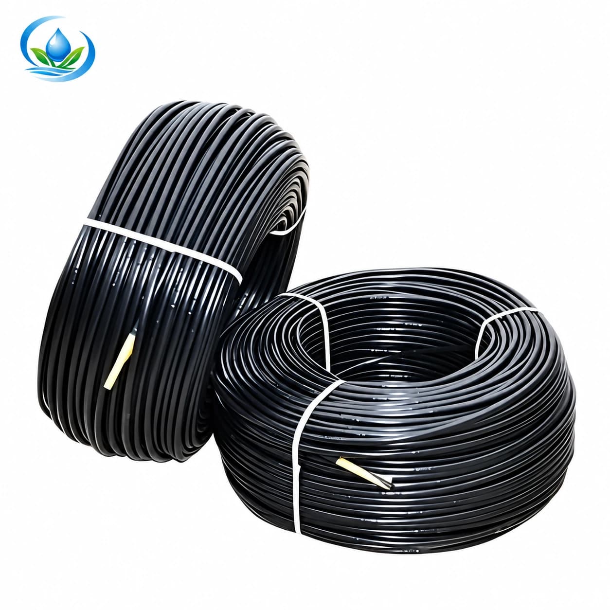
.jpg)