Drip Irrigation System Design: Flow, Pressure, Zones, and Uniformity
Design a farm drip system from measured supply, crop-row demand and a pressure budget. Learn how to size zones and choose compatible mainline, laterals and filtration.
Published by IrriNex Store
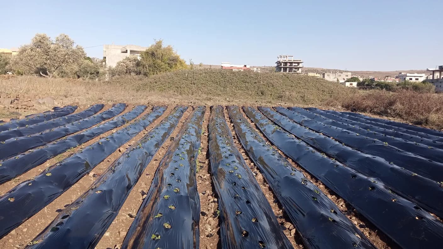
Drip irrigation system design begins with four facts: available flow, pressure while water is moving, the demand of each crop row, and the variation the field will add. Those facts determine how many rows can run together, which mainline diameter deserves a hydraulic check, whether drip tape or inline dripline suits the crop, and how much filtration and pressure control the system needs. This guide gives farm, orchard and greenhouse buyers a practical design sequence. It does not rely on a universal pipe-size chart. Instead, it shows what to measure, how to build a zone schedule, what to confirm on product pages, and how to test uniformity before installing the full field.
Define the design boundary before choosing components
Start with one block that can be operated and checked as a unit. Mark the water source, the highest and lowest points, the route available for the mainline, the position of each header and every crop row. Record row length and spacing rather than estimating from planted area. If the block contains different crops, slopes, lateral lengths or irrigation schedules, divide it on the drawing before doing the flow calculation.
The drawing should also show what already exists. Measure the pump outlet, storage-tank connection and installed pipe outside diameter. Identify the thread or flange standard. Note the pump model and any available curve, but verify performance in the field. A label stating a maximum flow or maximum head does not tell you what the pump delivers at the operating point.
Give every proposed zone a short name. A useful worksheet includes source test date, rows, metres per row, lateral type, emitter spacing, outlet flow, simultaneous demand, elevation range, target inlet pressure and expected operating time. This becomes the purchasing record and the commissioning checklist.
How to measure usable source flow at operating pressure
Flow and pressure describe different things. Flow is the volume available over time; pressure is the energy available to move that water through filters, valves, pipe and emitters. They change together as the operating point changes. A static gauge reading taken with every valve closed can look strong even when the source cannot maintain the required pressure at the planned zone flow. A farm drip irrigation system design comparison should keep the source reading and the calculated row demand in the same units before any zone boundary is drawn.
Test the source under a representative load. Use a calibrated flow meter when possible, or time a known volume for a smaller supply. Read pressure while that water is moving. Repeat the test when seasonal drawdown, shared pumps or storage levels can change the result. Record the weakest credible supply condition as well as the normal value.
Reserve pressure for each part of the route: source protection, the clean filter, control valves, fittings, elevation, mainline, header and lateral. A dirty filter will add more loss than a clean one, so the design needs an operating margin and accessible gauges. If the pressure budget is already exhausted before the lateral begins, a regulator cannot repair the design. It only reduces pressure; it does not create energy.
Calculate crop-row demand before grouping drip zones
Use the selected lateral specification, not a generic emitter assumption. For discrete emitters, multiply emitter output by the number operating in one row. For products rated by length, multiply the published flow per metre by the row length. Then multiply the row demand by the number of rows that will run together.
For example, a 90-metre row with outlets every 0.30 metre contains about 300 outlets. If the chosen option discharges 1.0 litre per hour per outlet at its specified test pressure, the nominal row demand is about 300 litres per hour. Twenty such rows would require about 6,000 litres per hour before adding any design or flushing allowance. This example explains the method; it is not a performance promise for a product family. Substitute the exact variant data and the pressure used by its manufacturer.
Compare the total with the measured source flow and the acceptable pressure range. If the block exceeds either limit, split it into zones. Keep rows with similar length, elevation and crop demand together. Zoning also provides control: a greenhouse variety with a short irrigation interval should not be locked to a distant orchard row simply because both use 16 mm tubing.
Build a pressure budget from source to farthest outlet
A pressure budget assigns part of the available pressure to every loss and elevation change. Begin with the measured dynamic pressure at the design flow. Subtract known losses through treatment and control equipment. Estimate pipe friction with a recognised hydraulic method or the pipe supplier's tables, using internal diameter, actual flow, route length and fittings. Include the header and the representative longest lateral.
Elevation changes pressure even when pipe size stays the same. A higher outlet has less pressure available; a lower outlet can have more. Long laterals add friction, and high flow at their inlet usually increases that loss. On uneven land, shorter zones, larger delivery pipe or pressure-compensating emitters may be justified. The choice needs calculations and field readings rather than a universal maximum-run claim.
Utah State University Extension's guidance on irrigation application uniformity describes a pressurised system as a source and filtration unit, main distribution, submain or manifold, laterals and outlets. It also explains that friction and pressure variation affect uniformity. That model is a useful independent check on the drawing.
Select the delivery pipe from the hydraulic schedule
The mainline must carry the largest simultaneous zone flow with tolerable friction loss and an appropriate pressure class. A connection that matches the pump outlet is not automatically the correct pipe size. A long mainline may need a larger diameter than a short header carrying the same water for only a few metres. Conversely, selecting the largest available diameter without a calculation can add cost, difficult handling and unnecessary transitions.
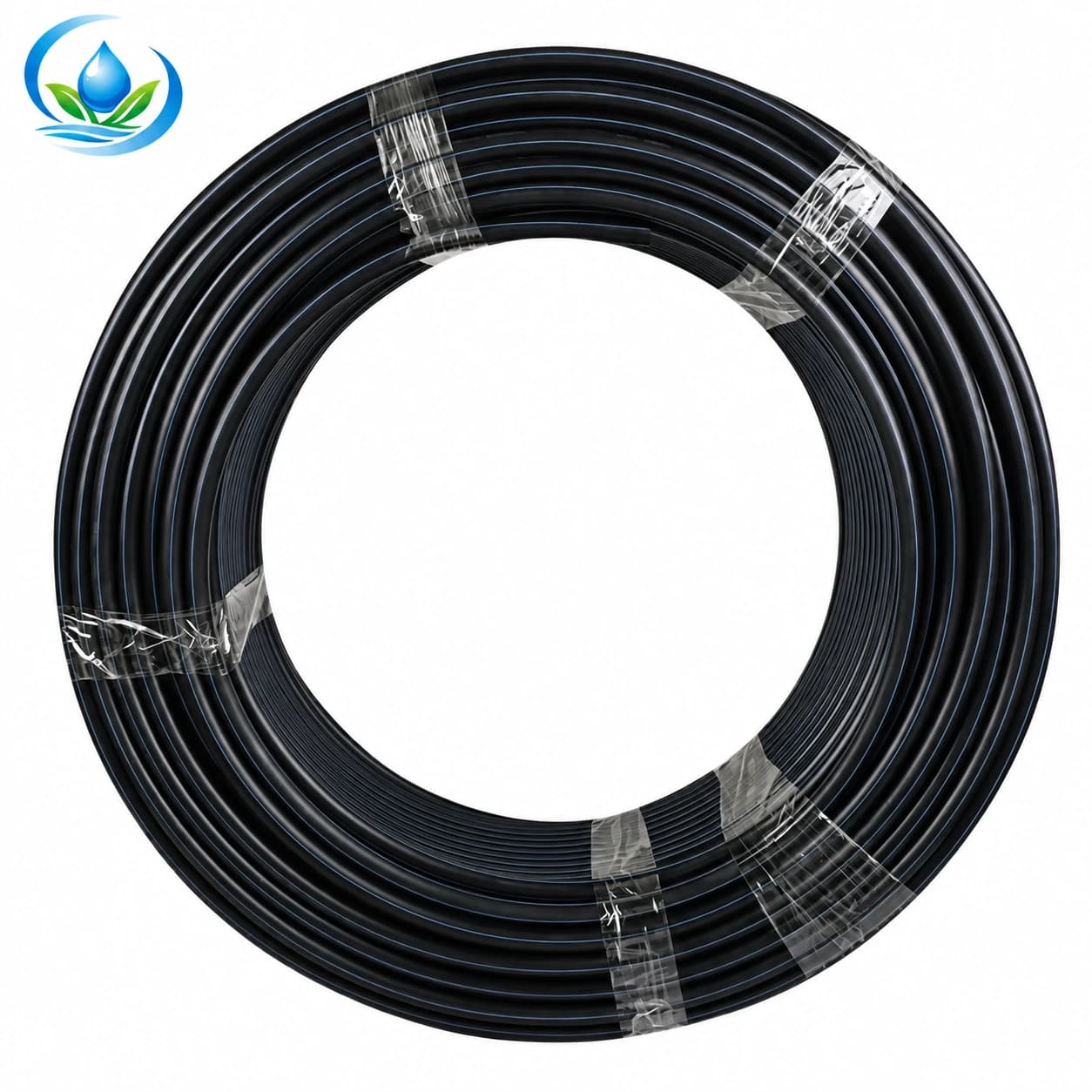
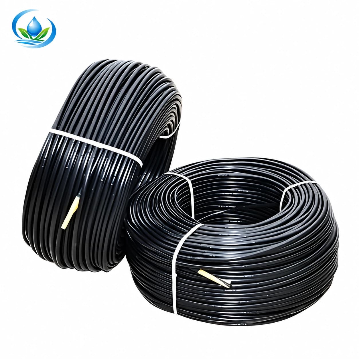
Use the PE irrigation mainline pipe page to compare the published 32–160 mm family, then request or use the dimensions and pressure class for the exact option. Size every tee, elbow, union, valve and adapter to that same connection system. Record whether a number refers to nominal size or actual outside diameter.
Lay out headers so row starts are accessible and flushing water can leave safely. Where the field is cultivated mechanically, protect crossings and decide whether the header will stay in place or be recovered after the season. Add isolation points that allow one block to be repaired without draining the entire farm network.
Choose drip tape or inline dripline for the crop cycle
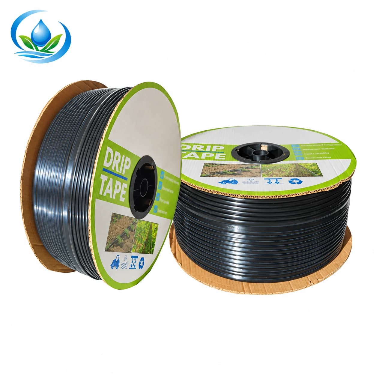
Seasonal vegetable rows often favour thin-wall tape because it can be laid quickly and purchased in long rolls. Reusable greenhouse bays, orchards and perennial rows often favour round inline dripline because it tolerates more handling. The decision also depends on pressure range, wall thickness, outlet spacing, discharge, retrieval method and expected years of service.
| Design input | What to verify | Purchase consequence |
|---|---|---|
| Crop and root-zone spacing | Emitter interval and expected wetted pattern in the soil | Choose spacing that supports the root zone without redundant outlets |
| Row length and slope | Manufacturer flow and pressure limits for the exact variant | Shorten zones or consider pressure-compensating products when justified |
| Crop cycle | Wall construction, handling and retrieval plan | Compare seasonal flat-emitter drip tape with reusable inline dripline |
| Water quality | Minimum passage and required filtration grade | Design treatment around the selected outlet, not around the pipe alone |
Do not mix fittings casually between tape and round tube. A 16 mm label may describe different dimensions or joining methods. Match starts, valves, couplers and end closures to the chosen lateral family and confirm the punch or header takeoff size.
Design filtration around water and emitter risk
The filter must serve the entire zone flow while protecting the smallest downstream passage. Record whether the source carries sand, silt, algae, plant fragments, precipitates or a mixture. Clean well water, a sediment-laden canal and stored surface water require different treatment plans. A laboratory water analysis and a field debris check are worthwhile for a large or high-value installation.
Compare filtration grade, rated flow, pressure limit, clean pressure loss and cleaning method. The connection size is only one selection factor. A small filter may physically connect to the mainline yet restrict flow or need attention several times during one irrigation set. Leave enough clearance to remove the element and install pressure test points where the pressure difference can be observed.
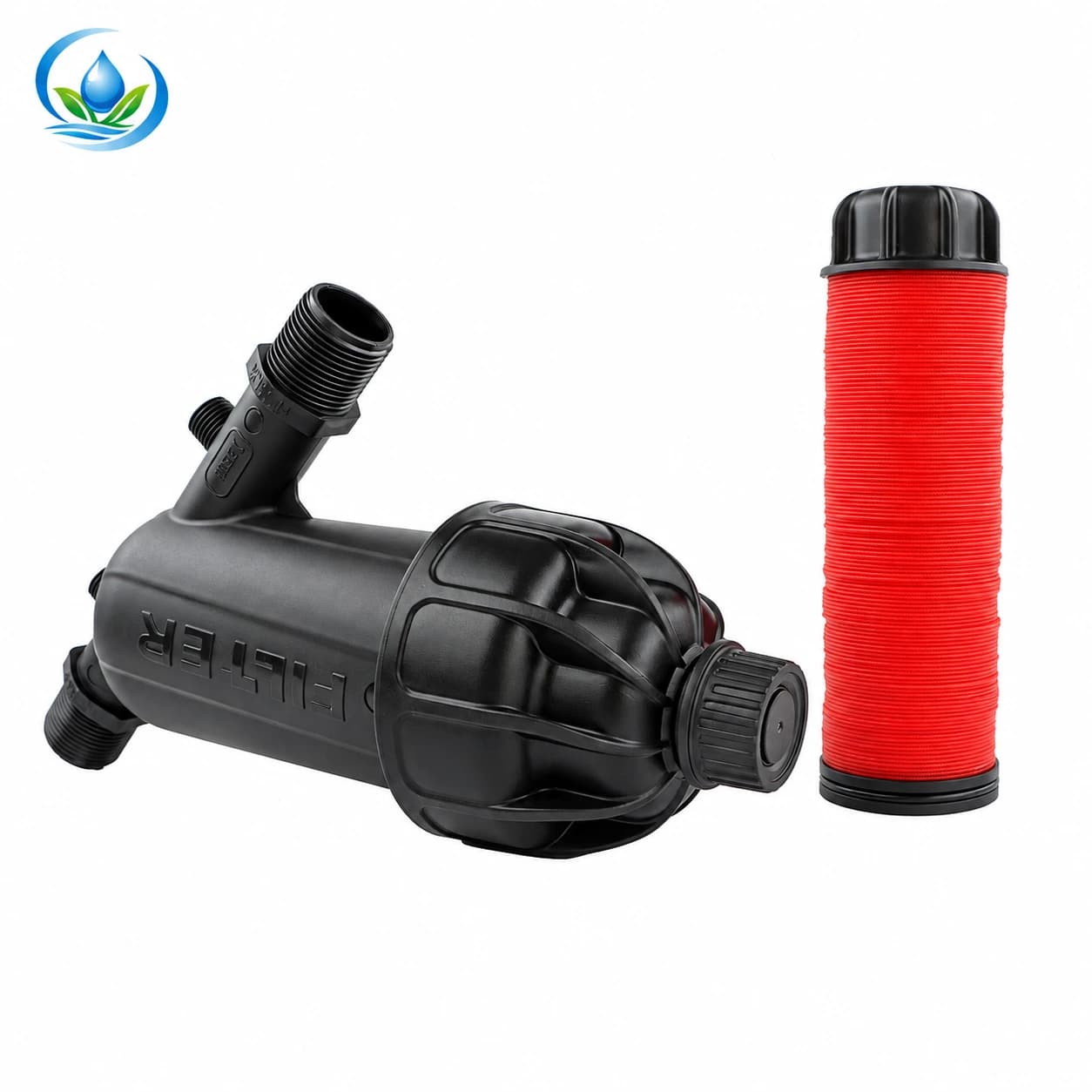
The Y-body disc filter provides selectable connection and filtration options for appropriate systems. Confirm the disc grade against the lateral requirement and the rated flow against the whole operating zone. Water with heavy organic load or sand may need staged separation or media treatment before a compact disc unit.
Plan valves, flushing and fertigation interfaces
Draw service parts before counting the order. The head unit normally needs isolation, pressure and flow measurement, filtration, pressure control when required and safe chemical-injection interfaces if fertigation will be added. Local backflow and chemical-handling rules govern source protection. Follow every equipment manual because the acceptable component sequence can change with the pump, regulator and injector.
Provide a controlled opening sequence for large zones. Opening every row valve at once can create a short high-flow condition and collapse pressure. Row or sub-zone valves make commissioning and repair easier, but each valve and fitting adds loss. Include them in the pressure budget.
Put reopenable flush points at the ends of mainline branches, headers and laterals. Route dirty flush water away from crops and electrical equipment. High points may need air-release or vacuum protection depending on terrain and system design. Low points may collect sediment and deserve deliberate service access.
Turn the drawing into a precise bill of materials
Count materials from the water route, not from memory. For each zone list mainline length, header length, control valves, tees, elbows, adapters, unions, gauges, row takeoffs, lateral length, couplers, end closures and flush assemblies. Add compatible repair parts and the exact tools for punching and cutting.
- For pipe: record outside diameter, wall or pressure class, joining method and total route with a measured installation allowance.
- For tape or dripline: record diameter, wall, spacing, output, operating range and roll length for the selected variant.
- For filters: record filtration grade, rated zone flow, pressure limit, connection standard and cleaning clearance.
- For fittings: name both sides of every transition and count the seals, clamps or grommets the joint requires.
- For instruments: select gauge and flow-meter ranges that can resolve normal operation rather than only extreme pressure.
The earlier agricultural drip irrigation component checklist can be used after the hydraulic schedule is complete. Keep the drawing, calculations and selected product options with the order so future repairs use the same standards.
Commission one representative zone
Install a representative zone before duplicating the layout. Flush the mainline and header before connecting laterals. Connect and flush the laterals, close the ends, then raise pressure gradually. Look for moving connections, twisted tape, kinks and filter restriction.
Measure pressure at the control head, at the beginning of a representative lateral and near its far end. Collect outlet water for equal time at several near, middle and far locations. Compare the volumes and investigate consistent differences. A wet patch beside the first row does not prove that the last row receives the intended amount.
Record clean-filter pressure, zone flow, inlet and end pressure, collected volumes, flush appearance and repairs. If results fall outside the design target or product limits, correct the mainline, zone size, regulation, filtration or lateral choice before scaling. This trial is part of design, not an optional inspection after purchase.
Use a pre-order design review
- Draw the source, elevation, mainline, headers, zones, rows and flush points.
- Measure usable flow and pressure at the same operating condition.
- Calculate demand from the exact lateral option and simultaneous row count.
- Prepare a pressure budget for the farthest representative outlet.
- Select delivery pipe, lateral, filtration and fittings by exact specifications.
- Count service access, gauges, valves, flushing parts and compatible spares.
- Test one zone and retain commissioning readings as the maintenance baseline.
Browse the agricultural drip irrigation range only after the worksheet is ready. When requesting help through IrriNex Store product support, attach the route length, elevation, measured flow, dynamic pressure, water-source description, row schedule and the links to the variants under consideration. Those facts allow a useful compatibility review.
Frequently asked design questions
How many rows can operate in one zone?
Divide the usable zone flow by the calculated demand per row, then confirm that the resulting group stays within the pressure budget and lateral limits. Reserve capacity for credible supply variation and service needs.
Can static pressure be used for design?
No. Static pressure is a useful diagnostic value, but the design needs pressure measured while the required flow is moving. Filters, pipe and valves consume pressure only when water flows.
Does a larger mainline guarantee uniformity?
No. It can reduce friction loss, but uniformity also depends on zoning, elevation, lateral behaviour, filtration, pressure control and installation quality.
Should the filter be selected before the dripline?
Select them together. The water source shapes the treatment train, while the chosen emitter sets the final protection requirement. Both must support the complete zone flow.
When is the design finished?
It is ready to repeat after a representative zone operates within component limits and the measured pressure and outlet volumes meet the project's uniformity target.
Design from measurements, then buy by specification
A durable farm system is the result of connected decisions. Source flow sets the ceiling; crop rows set demand; the pressure budget shapes pipe and zones; water quality and outlet passages shape filtration; field testing proves whether the design works. Keep those decisions visible in one worksheet and on one drawing.
That discipline makes retail comparison clearer. Instead of asking for “some 16 mm line” or “a large filter,” the buyer can compare exact spacing, output, wall, filtration grade, connection, pressure class and flow rating. The result is a system that can be installed, measured, maintained and expanded without guessing at every transition.
Before you order
Compare this guide with the specifications for your exact product, selected option, water supply and field conditions. Your equipment requirements take priority over a general example.
Compare irrigation products