Agricultural Irrigation Pumps: Check the Smallest Zone Before Buying
Check the smallest active zone, allowed changeovers, exact pump curve and controller behavior before choosing a solar or battery surface pump.
Published by IrriNex Store
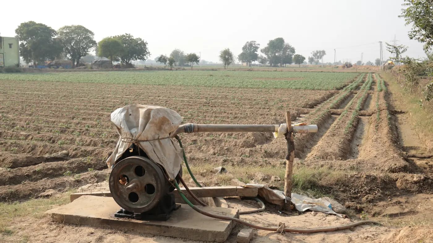
Agricultural irrigation pumps are often shortlisted against the farm's biggest watering block. That is only one operating case. If a smaller valve group runs on its own after harvest, during staged irrigation or while another block is unavailable, the same pump must also be suitable for that lower-flow duty. Before buying a new or replacement surface pump, list the smallest group you intend to operate and compare its flow and total head with the exact model's performance curve, permitted operating range and documented control arrangement. Check the pump curve for the smallest irrigation zone before buying, because a pump chosen for the largest block may not suit low-flow duty later.
The useful buying record is a set of allowed operating cases, not just a peak flow figure. Include the smallest active zone, the normal zone, the largest legitimate simultaneous demand and any valve changeover that the installed control scheme actually permits. Mark a case “unverified” where the outlet count, pressure loss, controller behavior or pump data are missing. Do not turn a catalogue maximum or a generic warning about cycling into a guess about how a particular pump will behave.
Size the irrigation pump for the smallest active zone
Draw the farm's normal valve schedule and name each group of outlets that can run without another group. Count the outlets that remain active when a crop row is removed, a nursery bench is isolated, a field section finishes first or the season changes. A small area on the map is not necessarily the lowest-flow case: a narrow block of high-discharge sprinklers can draw more than a larger block of low-output dripline. The farm zone-planning guide helps define what opens together; this page tests the resulting schedule against a pump.
Distinguish a legitimate planned small zone from an accidental restriction. An unexpectedly closed branch or clogged filter is a fault to address, not a new design case to normalize; a leak also changes delivery and must be repaired. Conversely, if the team routinely closes rows to work around a crop change, put that smaller configuration on the written schedule rather than relying on memory. Record the valve names, active crop rows, exact outlet variant, working duration and the person or control that starts and stops the pump.
Make a separate line for shared demand. A livestock point, filter backwash or another irrigation block that may run at the same time changes the flow through the pump. Only combine users when the operating rules permit them together; do not add all installed outlets as though every valve opens at once. If the smallest zone might operate alone because a shared user is turned off, that alone case needs its own check even if the normal combined case looked satisfactory.
Check the pump curve at low zone flow and required head
For each approved case, total the discharges of the outlets actually open at their specified operating conditions. Keep unlike nozzles and emitters on separate lines before adding. An outlet rate published at one pressure is not necessarily its discharge at another; obtain the exact product data instead of multiplying a convenient number from a different model. The drip-flow worksheet shows the outlet arithmetic, while the sprinkler head-count worksheet shows why a flow-only count still needs pressure and coverage checks.
Consider a wholly hypothetical illustration, unrelated to either Store pump. If 280 identical outlets are documented at 2 L/h each for the chosen condition, that group's nominal demand is 560 L/h, or 0.56 m³/h. If a separate group has 900 of those outlets, its nominal demand is 1,800 L/h, or 1.8 m³/h. If both groups are allowed to overlap during a changeover, their combined nominal outlet demand is 2.36 m³/h. If the control arrangement instead stops the pump between groups, that combined case does not occur. None of these figures is a minimum safe pump flow, an installed-system measurement or a recommendation to create overlap.
Beside each flow, record the required total head for that same case. Start with the delivery pressure required at the relevant outlets, then account for elevation from the operating water level and pressure losses through the actual filter, valves, pipe and fittings at that flow. Keep measurements, calculations and estimates identified separately. A static gauge reading with every zone shut is not a substitute for pressure at the outlets while water moves. The working-pressure checklist provides useful measurement locations.
The smallest zone may have lower pipe friction because less water moves, yet it may still require a high delivery pressure or sit above the pump. Its operating point cannot be inferred by shrinking the large-zone flow number while keeping the large-zone head unchanged. Conversely, a smaller demand may move the pump to a different part of its curve and alter downstream pressure. Check the flow-and-head pair for each allowed case, including the weaker source level or power condition relevant to that case.
Separate low-flow operation from controller cycling
Two different questions are often collapsed into “the pump is too big.” First, a pump commanded to keep running while a small zone draws little water may operate outside its manufacturer-permitted continuous range. Whether this is acceptable depends on the exact hydraulic curve, minimum permitted flow if specified, cooling or control design and installed conditions. A product's maximum flow says nothing about its permissible lower boundary. Do not invent a universal minimum or infer that an available bypass fixes an unknown design.
Second, a system with a documented pressure-operated start/stop control can switch repeatedly if its control and water demand do not match. That is a control-sequence question: inspect the installed controller specification and permitted starts, not a property automatically shared by all centrifugal, solar or battery pumps. A fixed-run system might keep operating at low flow rather than cycle, while another controller might respond differently. Confirm whether the selected pump and controller include a pressure switch, variable-speed control, dry-run shutdown or low-flow protection; the family name alone does not establish any of those features.
Ask what commands the pump to start, what tells it to stop, whether a valve opening is confirmed before the command, and what the approved sequence is during a zone change. A controller label, wiring diagram and manufacturer instructions are more useful than a picture of a similar pump. Have a qualified technician interpret electrical and control details. A grower's selection sheet can record the sequence and visible readings without opening a control enclosure, changing wiring or defeating a protective device.
List transition cases without creating a live no-flow test
A valve transition can briefly create a different demand from either steady zone. Some approved control schemes allow both valves to be open momentarily; others require the pump to stop before switching, and some use a documented tank or other engineered arrangement. Write only the states permitted by the actual controller and hydraulic design. If the transition is undocumented, mark it unresolved and obtain the manufacturer or installer's sequence before commissioning.
Do not close all valves against a running pump to “see the pressure,” force a dead-head condition, throttle the suction side, or assemble an improvised return line to make a catalogue model seem compatible. Any required control change, approved bypass, protected recirculation path or replacement pump needs a design specific to the model and installation. The buyer's task is to present the smallest and changeover cases clearly enough for that decision to be made.
A practical case table needs four rows even if some are later excluded: smallest approved zone alone, normal zone alone, largest allowed simultaneous group, and approved transition state. Add the source's operating water level, available electrical supply, clean and service-condition filter loss, required outlet pressure and expected flow for each. If a transition cannot happen under the documented control, cross it out with the reason. Do not replace a missing value with zero or silently assume every valve state is safe.
Read Store model maxima as limits, not a flow-at-head promise
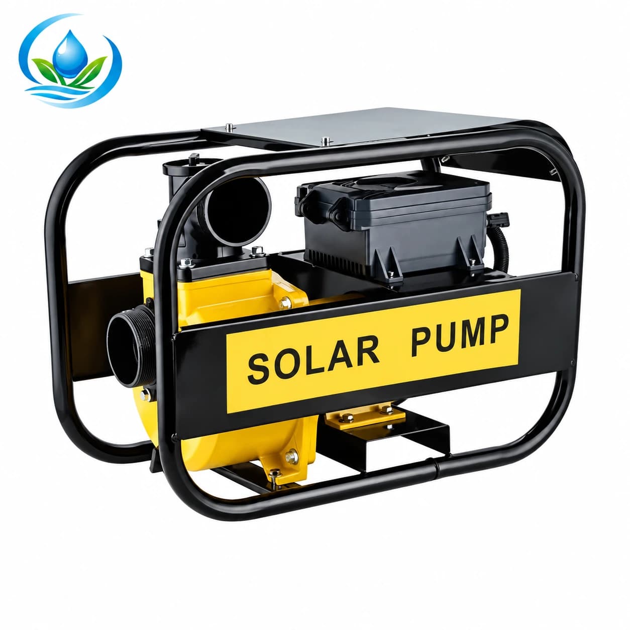
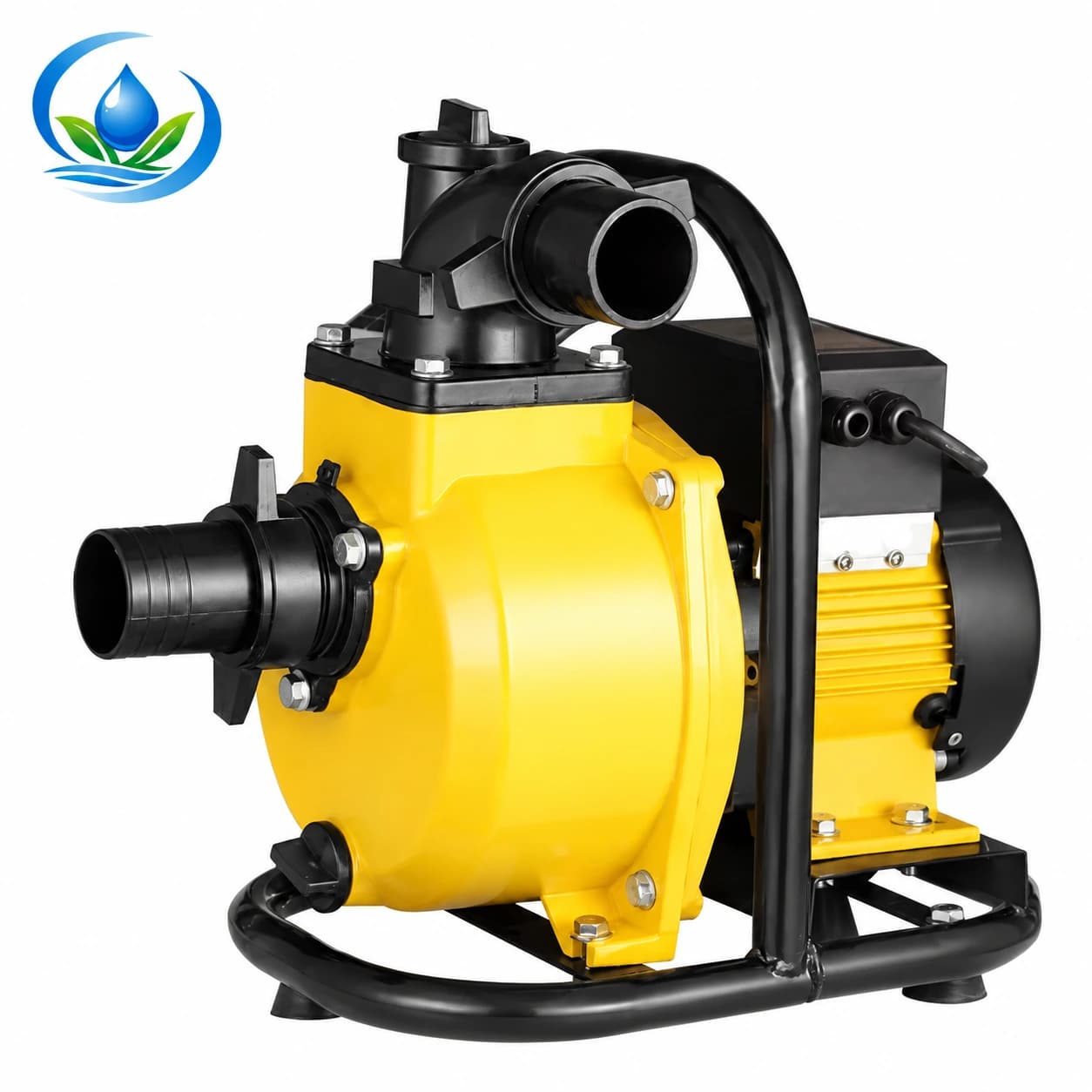
The IrriNex ZQD solar-oriented self-priming surface-pump family includes model ZQD8-30-72-750. Its catalogue row lists 72 V, rated power 750 W, maximum flow 8 m³/h, maximum head 30 m, a nominal 1-inch by 1-inch inlet/outlet entry and a 72–150 V working-voltage range. The IrriNex ZM battery-oriented surface-pump family includes model 25ZM6.5-25-48/72-750: 48–72 V, 750 W, maximum flow 6.5 m³/h, maximum head 25 m, nominal 1-inch by 1-inch connections and a 40–85 V working-voltage range.
These are two exact catalogue rows, not proposed substitutes for the hypothetical zones above. Neither row promises 8 m³/h at 30 m or 6.5 m³/h at 25 m. Nor does it show that a 0.56 m³/h example lies inside a permitted continuous range at the required head. Obtain a legible curve and allowable operating envelope for the exact model under the intended supply and controller conditions. If the available curve omits the low-flow end or permissible operation there, ask for explicit confirmation before selecting the model. Do not interpolate a duty point between separate maximum entries.
Power architecture remains part of the comparison. “Solar-oriented” does not establish which panels, controller or battery are included with a product option; “battery-oriented” does not authorize any battery assembly that happens to show a matching voltage. Confirm the permitted electrical arrangement and the items supplied for the selected code. The surface-pump family guide covers that broader power and source choice; the check here is whether the resulting exact model and controller can serve the smallest approved hydraulic case as well as the larger one.
Compare curves and controller documents case by case
Mark each calculated flow-and-head pair on the exact model's applicable curve. Confirm the curve's test conditions and the manufacturer-approved region, then check the whole set: small zone, normal zone, largest permitted group and any permitted transition. A pair that appears below a maximum head or maximum flow is not automatically on the curve or inside an acceptable operating range. A catalogue chart crowded with several model traces does not replace a readable exact-model curve and its operating instructions.
Use a decision column for each case: “supported by exact documentation,” “requires manufacturer clarification,” or “outside documented allowance.” Include the relevant power conditions and control mode beside the evidence. If one legitimate case remains unsupported, do not declare the model suitable for the full valve schedule. The solution might be a different pump model or an approved redesign of zones or control; it is not automatically a larger motor, extra sprinkler, arbitrary regulator or improvised bypass.
Watch for a tempting but invalid shortcut: a pump with a high maximum flow may still fail the farthest large zone at its necessary head and may also be unsuitable for the small zone. Conversely, a lower maximum-flow model may or may not cover both after exact curves are reviewed. This is why the purchase sheet should retain every duty point and the source condition behind it, not just the largest number in a brochure.
Make the purchase and first run traceable
Before ordering, retain the field map, valve schedule, outlet and nozzle references, calculated group flow, required head, source levels, filter and pipe-loss assumptions, exact pump curve, allowed range, controller sequence and selected power configuration. Confirm the exact option's current price, sale unit, availability, delivery and included components on its product page. If a purchase option is not displayed, ask IrriNex Store support how and when that model can be ordered before buying fittings or power parts around it. Confirm connection standards rather than treating two nominal 1-inch entries as proof of matching threads.
After an approved installation, a qualified installer can commission the documented operating cases with the normal water supply and intended controls. Record source level, supply status, active valves, inlet flow and working pressures at agreed points while the system operates normally. Observe the smallest and largest approved cases and the authorized transition without deliberately creating a blocked discharge or overriding a protection. Compare those readings with the accepted curve and field outlet requirements; retain the record for future seasonal changes.
If an existing pump begins stopping unexpectedly, losing delivery or showing alarms, preserve the observations and follow its own stop procedure. A small-zone mismatch is a selection question only after the actual source, controls and operating case are known. If a technician confirms that replacement is needed, use the replacement-pump dimensions guide to compare the selected unit with the mounting space and pipe positions before ordering. When crop rows are removed or valve rules change, update the case sheet before assuming the old pump remains suitable for the new smallest zone.
Before you order
Compare this guide with the specifications for your exact product, selected option, water supply and field conditions. Your equipment requirements take priority over a general example.
Compare irrigation products