Drip Irrigation Valve Leaking or Not Closing? Check Before Replacing It
Locate a leak at an installed manual drip valve, distinguish downstream drain-out from continued feed, and document the exact connection before requesting a replacement.
Published by IrriNex Store
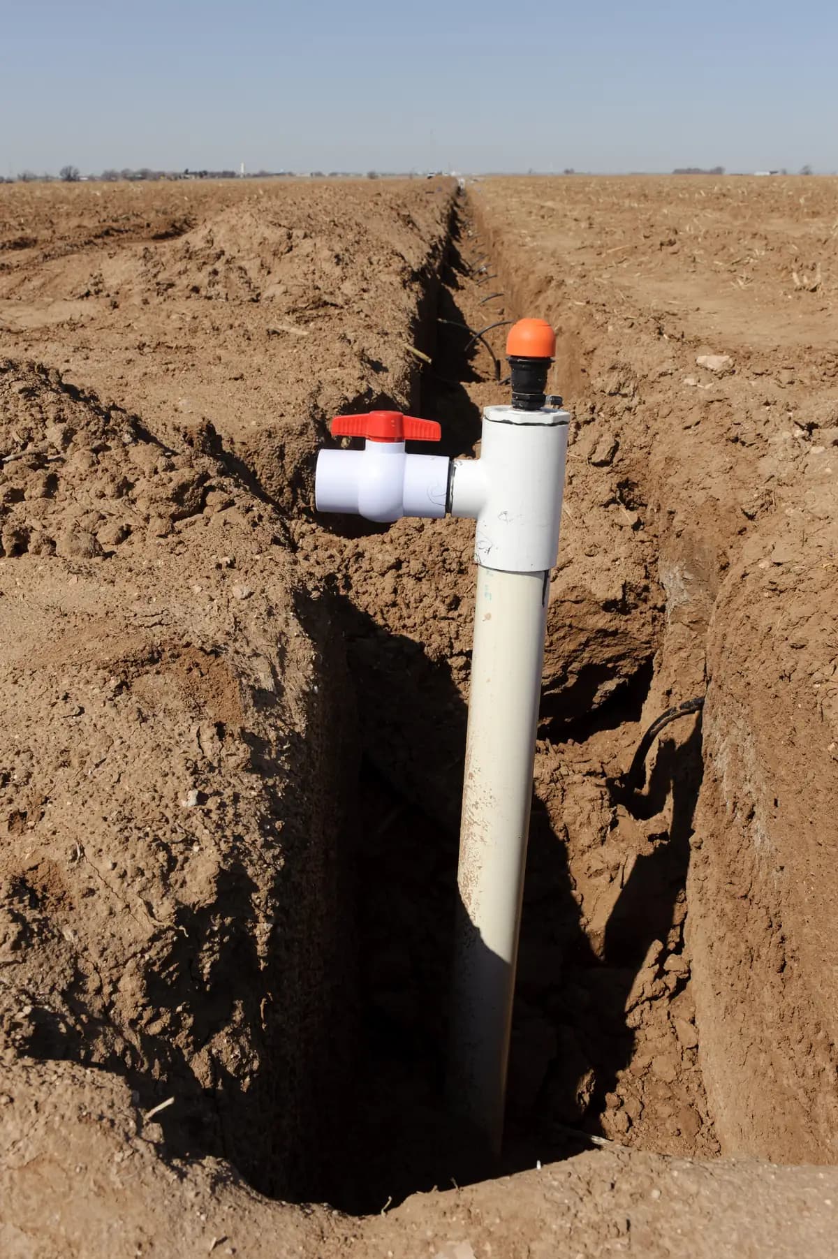
A drip irrigation valve that leaks or seems unable to shut a row off creates two different buying questions: is water escaping at the installed fitting, or is water still entering the downstream line? The answer determines whether to request a valve, a matching length of tube, a different connector, or a check of another feed. Make a short observation record while the system is operating normally, then isolate the water with a separate dependable upstream control before touching any joint. A suspect valve is not a safe isolation point. A drip valve not closing diagnosis should separate continuing supply from finite water already held downstream.
This guide is for an existing small manual valve on agricultural drip tubing. It concerns a field repair decision, not the initial selection covered in our manual valve buying guide. The catalogued choices discussed below are PE barb and lock-pipe families; instructions for a solvent-welded PVC ball valve do not establish how either one should be repaired or rated.
Is the drip valve leaking at a joint or through its outlet?
Before ordering anything, identify the side of the valve where water appears and the state of the system when it appears. Under normal operation, look from a safe position at the inlet connection, the body and handle area, the outlet connection, and the first visible stretch of tube. A droplet carried along the outside of tubing can make the valve body look wet even when the actual escape point is several centimetres away. Conversely, a dry outside surface says little about whether a closed valve is passing water internally. Record which zones were running and whether an automatic controller, tank, elevated header or neighbouring line might also supply the same lateral.
If the handle moves freely within its ordinary operating range, note its position before and after a normal closure. Do not apply a wrench, extend the handle, or push through a hard stop. A handle that is unusually stiff, broken or disconnected is itself a useful observation for the supplier, but forcing it can create a second failure and does not prove the internal closure state. If the system has high pressure, electrical equipment or an uncertain shutdown arrangement, stop the test and use the site operator or qualified technician.
- Water appears at an inlet or outlet joint: identify the exact joint, tube material, tube condition and connection style. The source may be a distorted tube end, damaged retention feature, incorrect size or a nearby split; the wet location alone does not prove the valve body has failed.
- Water emerges from the valve housing or handle region: photograph the point where it first appears and the moulded model code if visible. Treat a cracked or persistently leaking small body as a replacement query unless its own manufacturer gives a permitted service procedure.
- The outside remains dry but the downstream row continues to emit: observe the pattern and possible alternate feeds. Stored water, a cross-connected supply and actual internal bypass have different remedies.
Is water still feeding the row or merely draining away?
A closed manual valve can leave water already held in the downstream tube, laterals, headers and emitters. Gravity may move that volume toward lower outlets after inlet flow stops. A low point can therefore drip after the handle has been turned without demonstrating a damaged valve seat. The amount and duration depend on line length, elevation, emitter arrangement and connected volumes; there is no universal number of minutes that identifies a bad valve.
Watch whether the discharge becomes progressively weaker and ends, then compare it with another normal shutdown of the same zone if a safe baseline exists. Map the elevation: are the wet emitters below the valve or a raised header? Does another lateral share a manifold or feed the line from its far end? A tank, loop, siphon or second open control can replenish water that looks like leakage through the tested valve. Persistent flow deserves investigation, but it is not proof of a failed internal seat until the actual feed paths are understood. Our zone layout guide helps identify shared feeds; its design discussion does not replace this installed-valve diagnosis.
Keep the observation bounded. You need the start condition, what changed after the ordinary closure, the affected outlets, and whether the flow fades or remains clearly supplied. Do not repeatedly cycle a stiff valve, run a pump into an unsafe closed condition, or create a deliberate pressure test to settle the question. Where an unexpected feed is possible, the system diagram and a technician's tracing are more useful than guessing from the handle angle.
Isolate at a sound upstream point before inspecting a connection
If the suspect component is leaking or failing to close, it cannot be the only barrier between you and the water source. Find a separate, known-good upstream shutoff or stop the source according to the installation's operating procedure. Disable an automatic restart where the site procedure requires it, and follow the original pump, regulator and valve instructions for safely relieving trapped pressure. Confirm the specific section to be handled is no longer pressurized. Do not loosen a nut, cut tube, pull a barb, or open a valve body while pressure could remain. A surface that looks dry after shutdown is not a pressure gauge.
Only then perform external checks that the component maker permits: inspect the exposed tube for a visible split, flattening, hardening or abrasion; check whether the pipe is straight into the connection and supported rather than pulling sideways; and read the moulded code or label. If a locking component has a service instruction, use that exact instruction and its limits. Do not assume a sealed small valve has a replaceable seat, improvisable stem packing, generic washer or solvent-repair method. If you cannot identify its approved service steps, document the evidence and ask for a matched replacement.
Where the visible damage is on the tube, assess whether a sound end of the correct material and dimensions remains available for the manufacturer's connection method. A stretched, split or deeply scored end may prevent a reliable reseal even with a new valve. Our pipework leak-location guide follows the line beyond the valve; use it when the wet point cannot be confined to this component. If debris or uneven delivery is the main complaint and the valve does not leak, inspect the appropriate part of the system rather than treating every weak row as a valve fault; see the screen-filter service guide.
Match the installed connection, not the handle colour
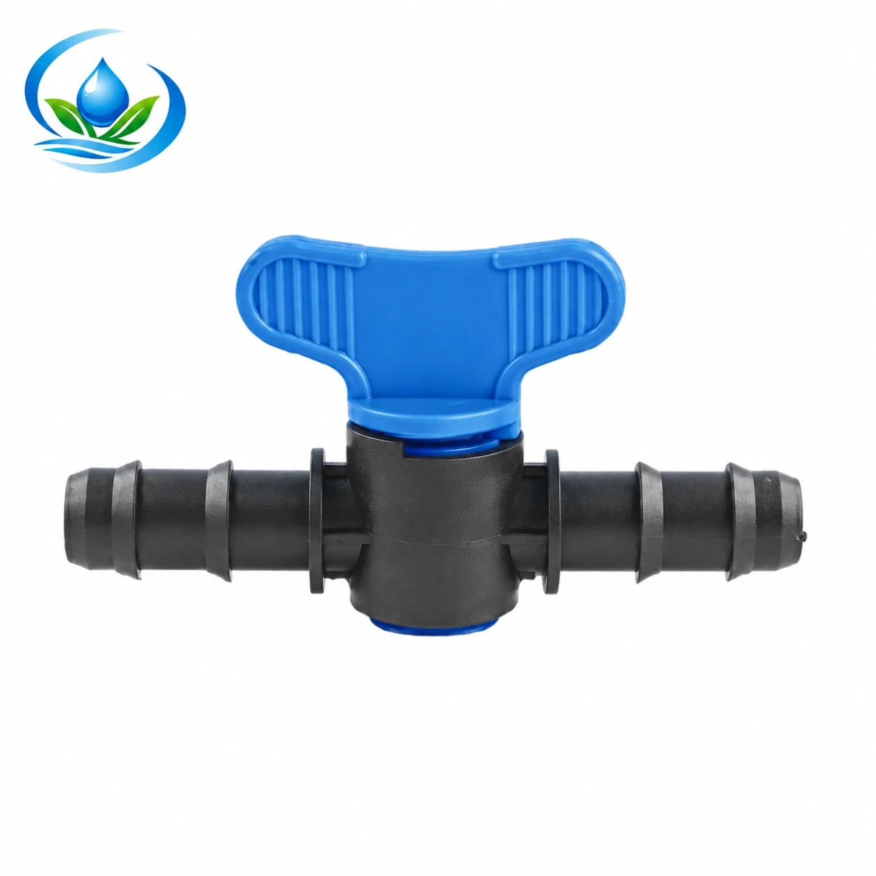
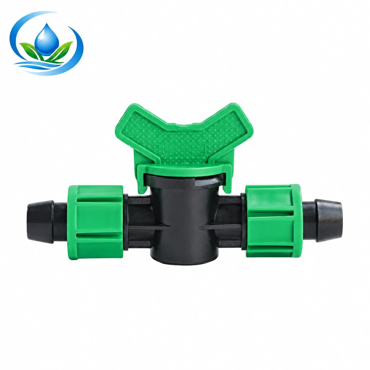
Two currently listed valve families illustrate why a request for “a 16 mm drip valve” is incomplete. The Maxi Valve (Blue Handle) is catalogued with V16A1 and V20A1 variants for nominal 16 mm and 20 mm connections. Its drawing and product image show an inline double-barbed arrangement. The Lock Pipe Coupler Valve has V16 at 16 × 16 mm and V20 at 20 × 20 mm, with locking connections on both ends. These are separate connection families. A blue or green handle in a photograph, or a nominal diameter alone, cannot certify that either will seal on the tube already in the field.
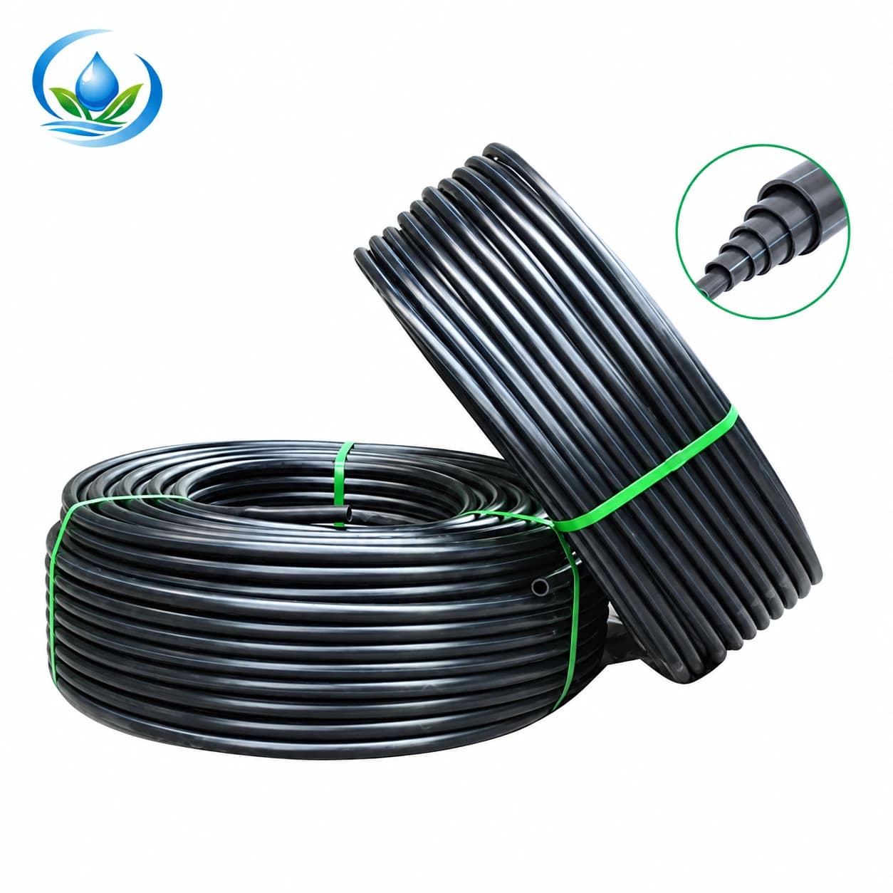
Read the installed item's code if possible and photograph both ends, including the retention detail, before removing anything. Measure the actual tube outer diameter and note its wall or inner diameter when available; also identify whether the line is round PE tubing, dripline, thin drip tape or another material. Check the maker's specified mating dimensions and assembly method for the exact valve variant and tube, including any service clearance. The blank PE lateral tubing listing has separately described 16 mm outside diameter with 1.0 mm wall, 20 mm with 1.5 mm wall, and 25 mm with 1.8 mm wall options. Those tube dimensions are useful to document a damaged length, but their coexistence in the catalogue does not prove compatibility with a particular valve or a field-worn line.
Likewise, a PVC slip socket joined with solvent is not a barbed or locking PE connection. A pressure figure, temperature limit, elastomer name or assembly instruction published for a PVC ball valve cannot be copied across to either Store family. If the existing part has threads, tape-lock ends, a different barb profile or a reducer, record that detail rather than ordering from a visually similar picture. Our fitting-family guide explains the distinctions among barbs, couplers and adapters; for this repair, the installed joint has the final say.
Choose a repair path from the evidence
Joint visibly leaking, body dry: request inspection of the tube end and the exact inlet or outlet fitting after safe isolation. If the tube is split or distorted, the material and sound cutback length may be the primary repair need. If the retaining piece is damaged, identify its approved replacement part or the complete matching valve. Do not assume tightening harder will restore a seal; it can crush a tube or damage a lock feature.
Body or handle region visibly leaking: note the model, installed orientation, operating condition and first visible escape point. Seek the original maker's service guidance. For a small sealed product without an identified service kit, requesting a complete matched valve is usually clearer than asking for an unspecified internal seal. Do not take an unknown body apart to discover what is inside.
Only downstream water after closure: determine whether it is a finite drain-down event, an alternate source, or genuine flow past the valve. Compare the same zone in comparable operating conditions if safe, and trace shared headers or return paths. A replacement order is premature while a second feed remains plausible. If the line receives continuing water only when the upstream source is on and all other feeds have been reliably ruled out, record that controlled observation for the maker or technician.
Handle will not move normally or is broken: leave it at a safe state and isolate elsewhere. A broken lever may make closure impossible, but replacing only the lever is justified only if the correct model has an approved spare and procedure. A forceful attempt can obscure the original failure and increase leakage. The supplier needs the code and photographs, not a guess about which internal component failed.
What to send with a replacement request
A concise, complete request saves a wrong purchase and a second shutdown. Include a photo of the entire installed valve and one close-up of each connection, the moulded code or measured dimensions, the tube material and diameter, the position of any lock nuts or barbs, and whether the body itself is visibly cracked. State which observation was made with supply on, which was made after an ordinary closure, and which was made only after a separate upstream isolation. Mention nearby high and low points, alternate feed paths and whether the row's discharge eventually ended. If there is no safe way to reproduce the symptom, say so.
Ask the supplier to confirm the exact variant and connection pairing, any manufacturer-approved service option, current price, available quantity and delivery for that SKU. For example, request V16A1 rather than merely “blue 16 mm” when the installed unit is positively identified as that Maxi Valve variant; request V16 only if the lock-pipe arrangement and mating tube are confirmed. These examples describe listed options, not a promise that either fits an unknown installation. If the tubing is also damaged, include its measured wall and required repair length so a valve is not ordered as the sole cure.
Verify the repaired zone without creating a new fault
After a qualified or manufacturer-directed repair, return the system to service using its ordinary start-up sequence. Observe the repaired joint and the body under a normal operating condition, then compare downstream response to the recorded pre-repair pattern. Confirm that other rows on the same zone still receive their expected flow and that a line has not been accidentally left isolated. Follow the site's pump and controller procedure; do not dead-head a pump, repeatedly start it dry, or use a higher pressure simply to “prove” a seal.
If a sound replacement still shows a wet outside joint, revisit tube condition and mating dimensions before condemning another valve. If the outside stays dry but downstream flow persists, revisit the supply map and drain-out possibilities. The repair is complete when the actual escape or continued feed has been explained and the zone operates as intended, not merely when the handle looks closed. For broader checks after a dormant season, use the seasonal zone restart guide; this valve-specific record remains the basis for deciding which component, if any, to buy.
Before you order
Compare this guide with the specifications for your exact product, selected option, water supply and field conditions. Your equipment requirements take priority over a general example.
Compare irrigation products