Irrigation Tubing: Match the Punch and Mark Outlets Before Installing Emitters
Mark actual outlet positions in identified blank PE, match the punch opening to the chosen stem and wall, then inspect a permitted sample hole before repeating.
Published by IrriNex Store
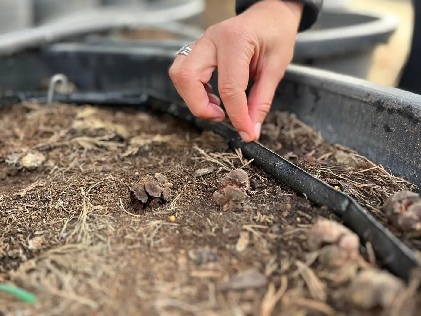
Irrigation tubing should be marked for its actual emitter or microtube take-off positions before anyone makes the first hole. An opening in blank polyethylene (PE) feed cannot be moved after it is punched, and a neat-looking hole may still leak if the tool tip, tube wall and outlet stem were never approved as one combination. Identify the tube and intended outlet first, make one permitted test hole in matching offcut, examine both tube walls and the fitted outlet, then decide whether the method can be repeated across the crop block. Mark blank PE irrigation tubing outlet positions before punching, so each selected emitter serves the actual plant position rather than an assumed interval.
The practical purchase is a matched tool and outlet plan, not a bag of nominally similar diameters. The field record should show each proposed outlet position, the precise pipe option and wall, the emitter or take-off fitting code, its specified preparation opening, the selected punch model and the result of the trial. A 3 mm or 4 mm punch name is not proof that any connector called ¼ inch will seal in the hole. Nor does a 16 mm pipe label by itself prove that the wall may be punched.
Mark outlet locations on blank PE irrigation tubing
Walk the crop rows and identify where water should leave the blank PE, using the planting plan and the chosen outlet's delivery pattern. A point emitter may sit in the tube directly, or a take-off fitting may supply a short microtube to a stake or container. Those are different physical connections at the supply wall even if they finish near the same plant. Mark the downstream water point and the reachable take-off position separately so a later adjustment to a pot or vine does not pull on the hole.
Record the exact row, plant or container group, intended active outlet model, and whether that outlet will operate with the other holes in the same zone. The number and flow of active outlets must already fit the zone's hydraulic plan. The point-emitter selection guide covers outlet behavior and quantity; this guide deals with placing and preparing the accepted openings in a specific blank tube. Do not choose a convenient regular hole spacing merely because the punch is ready. The required positions depend on the crop layout and delivery design.
Keep future changes visible on the drawing but do not punch openings for hypothetical plants. A temporary unused hole needs a verified small-hole repair part, not a full-bore end plug. The hole-and-end closure guide explains that distinction. If the present crop needs an added branch rather than one point take-off, assess the existing and new simultaneous demand before cutting or punching the supply. The crop-bed expansion guide covers that separate hydraulic decision.
Test the punch and outlet combination on matching offcut
Read the pipe label or purchasing record and inspect a sound exposed section. Record the manufacturer's identity, outside diameter, wall specification and exact option. Do not identify the material by colour alone. Flat drip tape and round inline dripline already contain factory outlets; puncturing them by analogy with a blank PE feed can damage an emitter path or create an unsupported leak. A rigid or reinforced pipe may require a completely different approved outlet method. Confirm that the original tube maker allows a punched take-off in the selected location and wall.
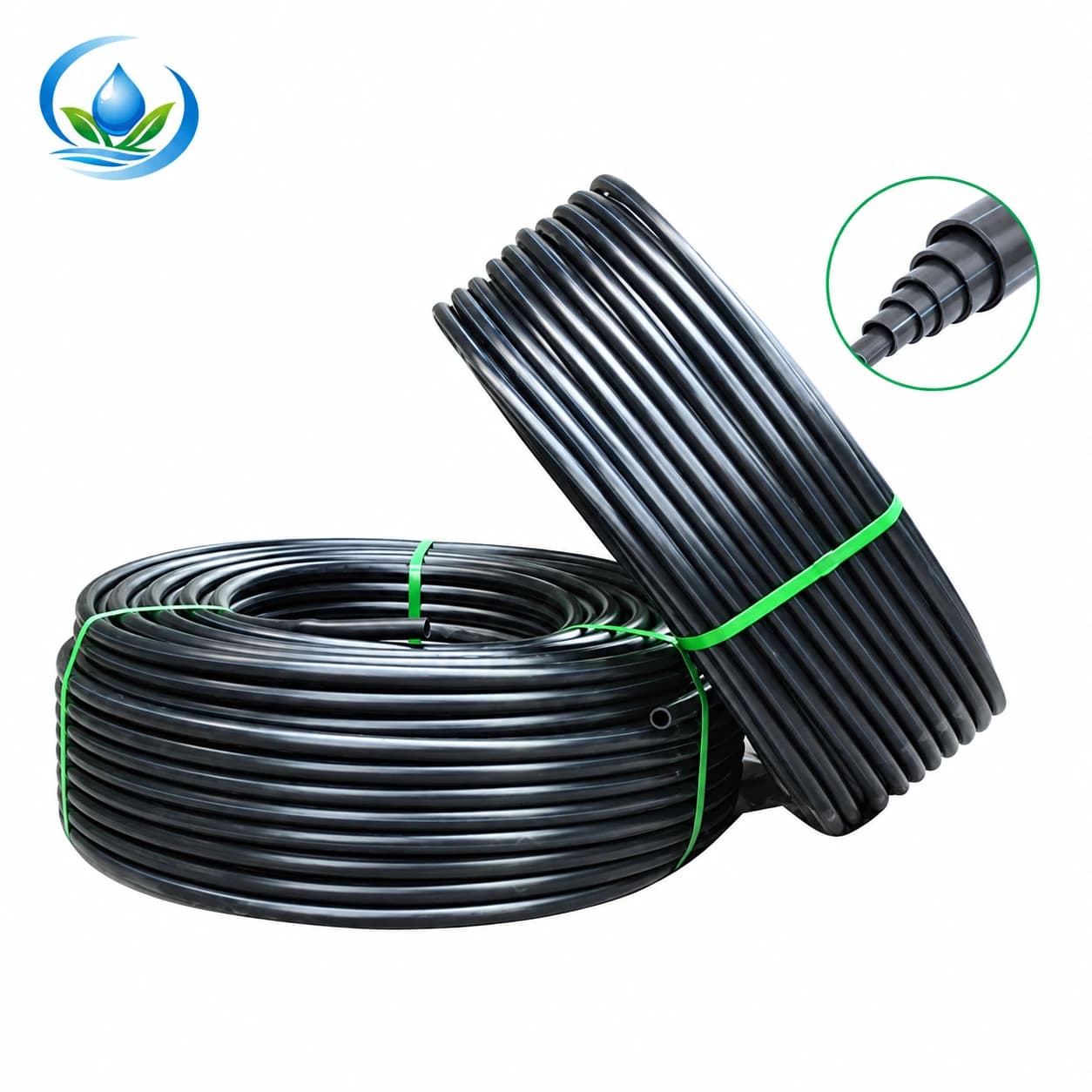
The IrriNex blank PE tube lists option IS-4-DD62380CF7 with 16 mm outside diameter and 1.0 mm wall; IS-4-9949192827 pairs 20 mm outside diameter with 1.5 mm wall, and IS-4-FF374FF9AC pairs 25 mm with 1.8 mm wall. These are distinct size options from the original catalogue. None of those paired dimensions specifies a compatible hole or confirms that every model can accept an arbitrary barb. Obtain the original pipe and outlet instructions for the actual selected option before preparing the wall.
Locate a clean offcut from the same identifiable tube lot, or a spare sample that matches material, outside diameter and wall. An old mystery scrap is a poor acceptance test for a new coil. If a previously installed line has hardened, flattened or been abraded, a successful hole in fresh scrap may not certify the old line. Mark the uncertain section for separate review. The PE routing guide explains how to keep the feed supported and free of sharp creases before outlets are added.
Match the punch tip to the fitting's opening requirement
Ask what preparation hole the specific emitter or take-off stem requires in the chosen tube construction. A product's “4 mm” label might refer to its inlet barb, outlet barb, microtube bore or something else; it is not automatically a 4 mm punched-hole instruction. Likewise, “¼ inch” on another supplier's fitting is not a conversion rule for either punch. Compare the selected fitting maker's hole and insertion guidance with the pipe maker's wall guidance and the tool's stated hole size. If any side of that pair is undocumented, do not make production holes by guesswork.
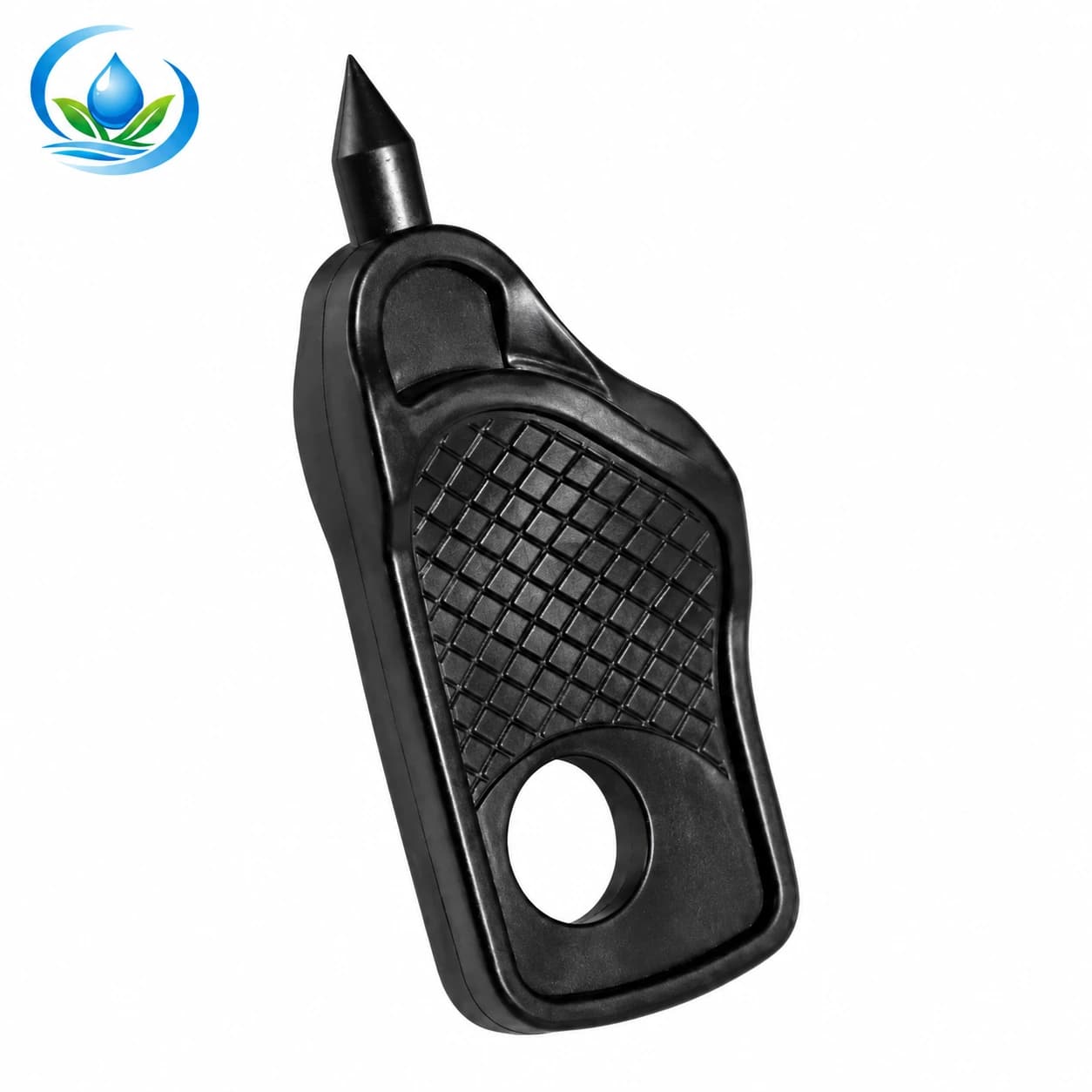
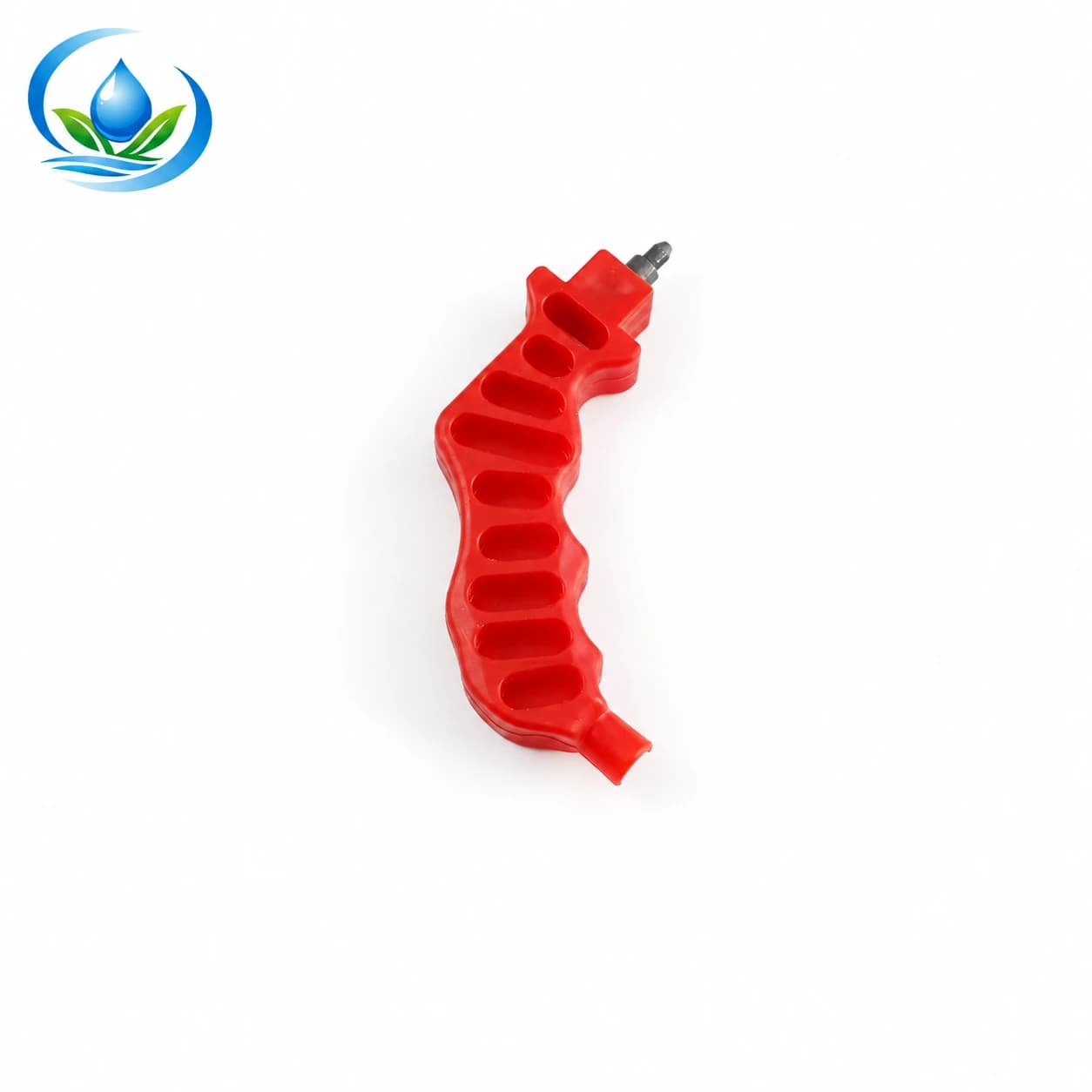
The XF1301-01A hand punch is the current catalogue's nominal 4 mm hole option. The separate XF1301-02A hand punch is its nominal 3 mm hole option. Their exact codes and sizes are paired in the original punch-tool catalogue and the current product options. These labels tell you the nominal prepared opening, not the range of tube walls each tool can safely penetrate or the stems it will hold.
Inspect the selected tool before use. Confirm its code on the product and supplied packaging, see that the tip is present and undamaged, and use the maker's handling and tip-clearing instructions. A bent or blunt tip can stretch or tear the opening rather than prepare the specified shape. A tool that looks similar in a photograph may be a different size. Do not use a nail, drill bit, knife or heated implement as an improvised substitute for the verified punch.
Turn the field marks into an inspection-friendly hole plan
Once the outlet models are fixed, make a durable mark for each planned take-off on an accessible side of the blank tube. Keep the mark clear of a bend, abrasion, previous hole, fitted connector or place where an attachment will be loaded by crop work. Do not assume a universal distance from those features; use the selected tube and outlet maker's spacing and placement guidance. If the desired water point is several steps away, route and support the proposed microtube first so its supply fitting is not forced into an awkward position.
Look along the tube before approving a row of marks. Ask whether an installer can approach each position squarely with the intended tool and keep hands clear of its point. A mark hidden under mulch or beside a stake may be easy to draw on paper but awkward to punch and difficult to inspect later. Separate the hole positions from endpoints and existing repairs. The fittings guide helps distinguish an inline joint or tee from a small outlet take-off; do not use one name for all those jobs.
Count only the holes planned for the present operating case. For each row, record the number of direct emitters, the number of microtube take-offs and the model attached to each. A branch with three remote stakes may need a documented manifold or multiple individual take-offs; that is not decided by counting visible plants alone. The nursery endpoint guide shows why a terminal stake, upstream metering device and supply connection must be identified separately. The hole plan should name the supply-side stem, not merely the object visible by the root zone.
Make one approved trial opening in matching scrap
Use a spare piece only after the tube, fitting and punch pair has been approved from their instructions. Secure the sample in the way specified for the tool, keep fingers clear of the tip and approach the target wall squarely. Work on a stopped, isolated and depressurized line when a sample comes from an existing system. Do not press a tool into live pressurized pipe. Avoid driving the point through both walls: the intended take-off should open the near wall only, under the selected product's method.
Inspect the outside of the sample before inserting anything. The intended single opening should be at the mark, with no split leading away from it, large flap or stretched oval. Look inside where the method permits to confirm the far wall has not been pierced and that plastic pieces have not been left in the water passage. Do not probe the sharp tool tip or clear it with a bare finger. Follow its maker's safe debris-removal method; a chip left inside may travel toward an emitter.
Insert the exact fitting or emitter stem in the test hole according to its instructions, without inventing an insertion depth or forcing a larger barb into the wall. Observe whether the tube is distorted, whether the fitting sits as specified and whether the assembly can be supported without side load. If the hole tears, the stem cuts the wall or the product requires excessive force, stop and recheck the three-part match. Making the rest of the holes first would multiply the same defect across the entire field.
Check the first fitted outlets under normal operating conditions
After the dry trial, connect a representative sample to the intended equipment by its approved sequence. Protect sensitive outlet passages during any required commissioning flush, following the actual system instructions. Restore the normal filtration and pressure regulation, then run the operating group within the documented limits of tube and outlet. Check the test connection for a slow weep, movement or wall deformation while the complete relevant zone is flowing. Do not use elevated pressure as a proof test for an uncertain hole.
Observe delivery at the newly fitted point and compare it with the selected outlet's expected behaviour under the same operating condition. If a microtube leads to a remote point, check both its supply take-off and terminal outlet; a dry hole at the PE wall does not mean water reached the plant. If the first sample leaks, isolate and depressurize according to the equipment manual before touching it. Record whether the problem is the prepared hole, outlet stem, tube condition, insertion or running pressure rather than assuming the tool alone caused it.
An accepted sample helps evaluate the documented method for the same confirmed combination and comparable tube condition; it does not certify every metre of old pipe. Keep the accepted sample, a photograph and its code with the block record. If a different emitter stem, tube wall or punch model is introduced mid-row, make a new compatibility decision and trial. If the end of a line delivers weakly after outlets are added, review the zone's operating demand and pressure as well as the individual holes.
Repeat carefully and stop when a hole changes character
Work through the marked line in a sequence that keeps the remaining marks visible and protects unfinished openings from soil. Follow the tool's handling instructions at each point rather than relying on how the first hole felt. Check the tube wall and position before every press. On a long block, pause to compare new openings with the accepted sample; a damaged tip or an unexpected wall change may show up as ragged edges or harder insertion.
Fit each outlet by its maker's method and keep unsupported microtubes from pulling the new take-off sideways. Record which row and outlet codes were completed. Before closing or covering the area, perform the system's required debris-clearing and return-to-service steps with sensitive components protected as specified. A few clean sample holes do not prove that a complete row has no leaking fittings or accidentally double-punched positions. Walk the operating row and inspect representative near and far outlets.
If a hole is enlarged, torn, misplaced or left unused, stop and mark it as a separate repair decision. A full-bore end cap will not seal a small emitter opening, and an unknown plug is not a safe substitute. Use a repair piece only if its exact hole, wall and pressure application is verified. If no suitable piece exists or the material around the hole is unsound, follow the tube maker's cut-out or replacement route after isolation. Do not keep inserting a bigger fitting to conceal an oversized opening.
Choose the exact tools and preserve the accepted pairing
Before checkout, compare the intended fitting's documented hole requirement with the 4 mm XF1301-01A and 3 mm XF1301-02A product pages. Select the punch for an approved pairing, not because one is cheaper or a familiar colour. Check the actual item, unit, current price, availability and delivery on its product page. For the PE tube, use the exact outside-diameter and wall option already accepted in the sample; a listed size alone is not a promise that every crop block or outlet stem can be punched in it.
Keep the field's accepted pairing card: tube option and lot, wall, outlet model and stem, required hole, punch code, sample date, observed operating condition and any approved cleaning or replacement method. That card helps a second installer repeat the work without converting “3 mm,” “4 mm” and “¼ inch” into informal synonyms. Store the punch with its code and protected tip. If a replacement tool arrives with a different model marking, verify it again before using the old hole map.
| Before repeating a hole | Evidence to keep | Stop if |
|---|---|---|
| Outlet location | Named row, water point and accessible take-off mark | Crop access or branch position has changed |
| Tube | Maker, exact blank PE option, lot and approved wall | Material is unidentified, damaged or emitter-bearing |
| Tool and fitting | XF1301 code, hole requirement and exact stem model | Nominal numbers are the only claimed match |
| Scrap trial | Clean near-wall opening, intact far wall and seated part | Hole tears, stretches or penetrates both walls |
| Operating trial | Leak check and outlet delivery in the intended running group | Joint moves, seeps or fails to supply the water point |
Mark the field positions, prove the exact tube–punch–outlet combination on matching scrap, and inspect the first installed points in the real operating group. Continue only while the repeated holes match that accepted result. When a location or component differs, resolve that difference before making a permanent opening in the crop line.
Before you order
Compare this guide with the specifications for your exact product, selected option, water supply and field conditions. Your equipment requirements take priority over a general example.
Compare irrigation products