Drip Emitters Buying Guide: Flow, Pressure Compensation and Quantity
Choose point-source drip emitters by flow, pressure behavior, connection, filtration, lateral capacity and the number of crop watering points.
Published by IrriNex Store
Drip emitters are point-source outlets that meter water from a lateral at individual crop plants, containers or selected root-zone positions. A useful order starts with plant count and water demand, then matches nominal flow, pressure behavior, connection, filtration and lateral capacity. This buying guide compares fixed non-compensating, pressure-compensating and adjustable emitters, calculates how many a zone can support and lists the small parts required to install and test them.
Confirm that a point emitter is the right product
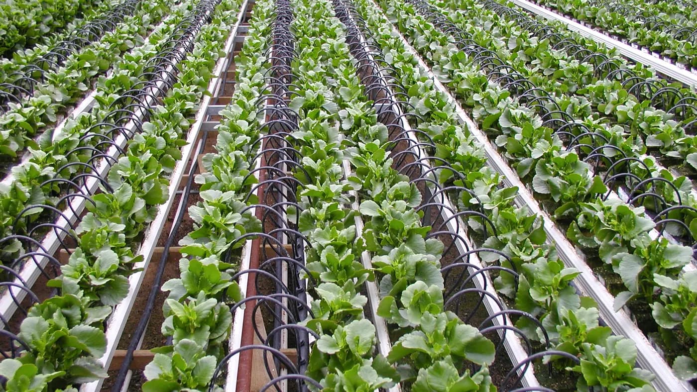
Point emitters let the grower choose a watering location for each plant. They can be inserted into a compatible PE lateral or feed a remote point through micro tubing. This layout can suit spaced orchard trees, vines, greenhouse pots and other crops where planting positions are known and individual outlets remain accessible.
Inline dripline and drip tape solve a different purchase problem: their outlets are manufactured into the lateral at regular spacing. They may be faster to lay through continuous crop rows. Review the drip tubing comparison if the field has dense, repeated spacing. Do not buy hundreds of point emitters until the layout shows that individually placed outlets provide a practical advantage.
Count plants and watering points before ordering emitters
Count plants inside each irrigation zone and assign planned watering points to each plant. Young trees may begin with fewer points than mature trees, while a large root zone may need water distributed around more than one position. Containers often use one or more stakes supplied from a point emitter. Record current needs and leave a documented expansion path. A crop-row drip emitter count should count active plant positions separately from spare pieces and then total the flow of outlets running together.
Do not apply a universal one-emitter-per-plant rule. Flow, run time, soil or substrate, root distribution, plant growth and climate determine the useful number. A high-flow point can create runoff or a narrow wet pocket while the rest of the root zone stays dry. Several lower-flow points may distribute water more broadly, but they also increase zone flow and parts count.
Choose nominal emitter flow together with the watering schedule
Emitter discharge is commonly listed in litres per hour or gallons per hour. It describes a nominal output under the documented operating conditions, not the amount a crop automatically needs. Planned water per point equals emitter flow multiplied by run time. Two 4 L/h emitters operating for one hour plan eight litres to a plant before allowance for field variation.
Compare 2, 4 and 8 L/h options by the run time they create. A very low flow may require a long window; a high flow may exceed infiltration or shorten injection and flushing time. For different crops in one zone, changing the number of equal-flow emitters is often easier to audit than mixing many colours and outputs. Verify every selected variant because colour conventions are not universal.
Understand fixed non-compensating emitters
A basic fixed emitter has a nominal rating, but its output generally changes with inlet pressure. Near the head of a long lateral it may receive more pressure than an outlet at the far end. Elevation can add another difference. The device may be a cost-effective choice where runs are modest, terrain is level and measured pressures stay within a suitable, narrow range.
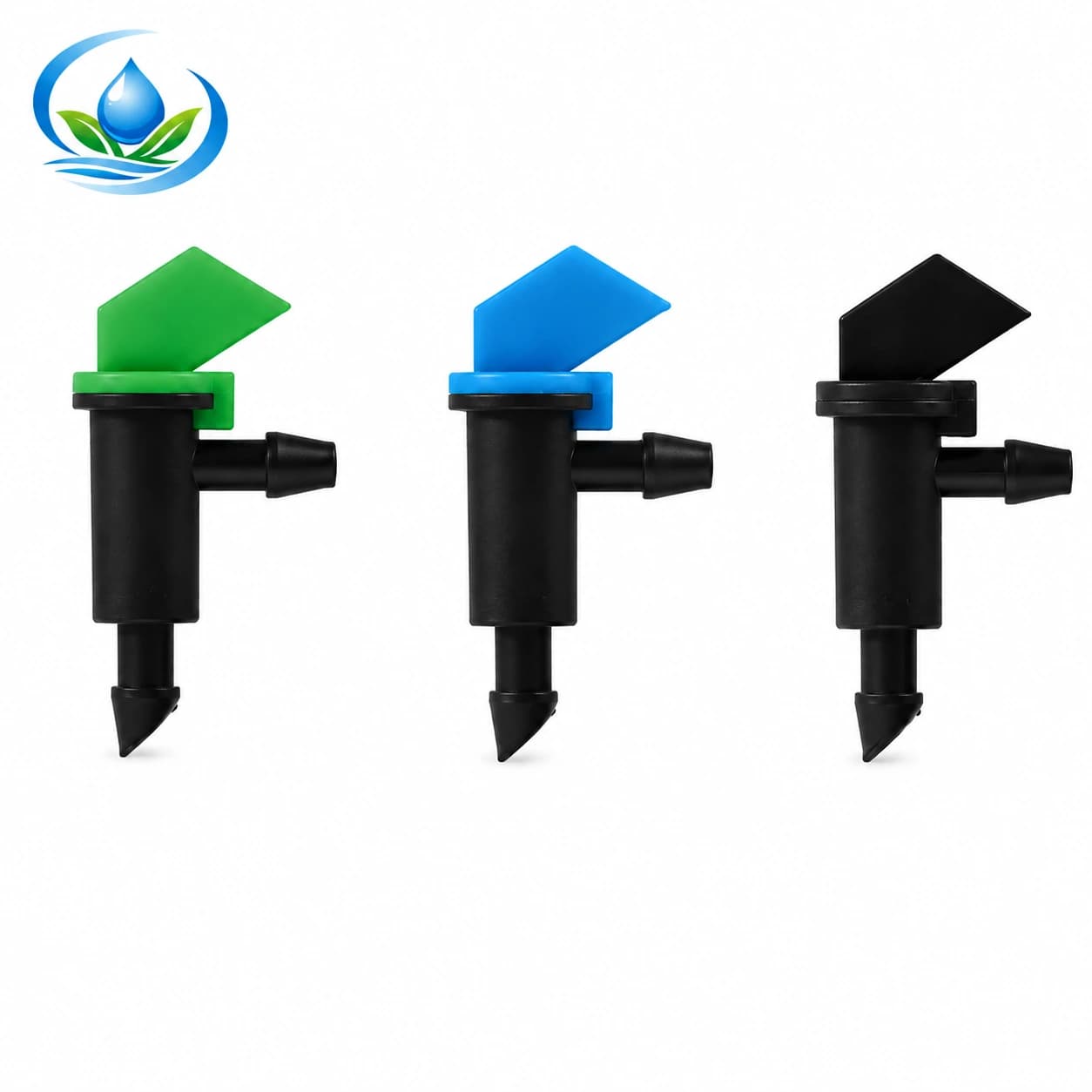
The flag-style drip emitter offers current listed choices of 4, 8 and 16 L/h. Treat those as separate selection variants. Do not call the product pressure compensating or adjustable. Confirm its connection, operating requirements and cleaning method on the current page before ordering.
Understand pressure-compensating emitters
A pressure-compensating emitter uses an internal element to keep discharge closer to its nominal value across a stated pressure range. It can help when a lateral experiences meaningful pressure change because of length or elevation. Compensation begins only after the device reaches its documented operating condition and ends outside the specified range.
It cannot create missing inlet pressure, correct an undersized lateral or overcome a blocked filter. Utah State University Extension advises designers to minimize pressure differences or use suitable pressure-compensating emitters in its small-farm irrigation practices. Apply that principle with the selected manufacturer's current performance data.
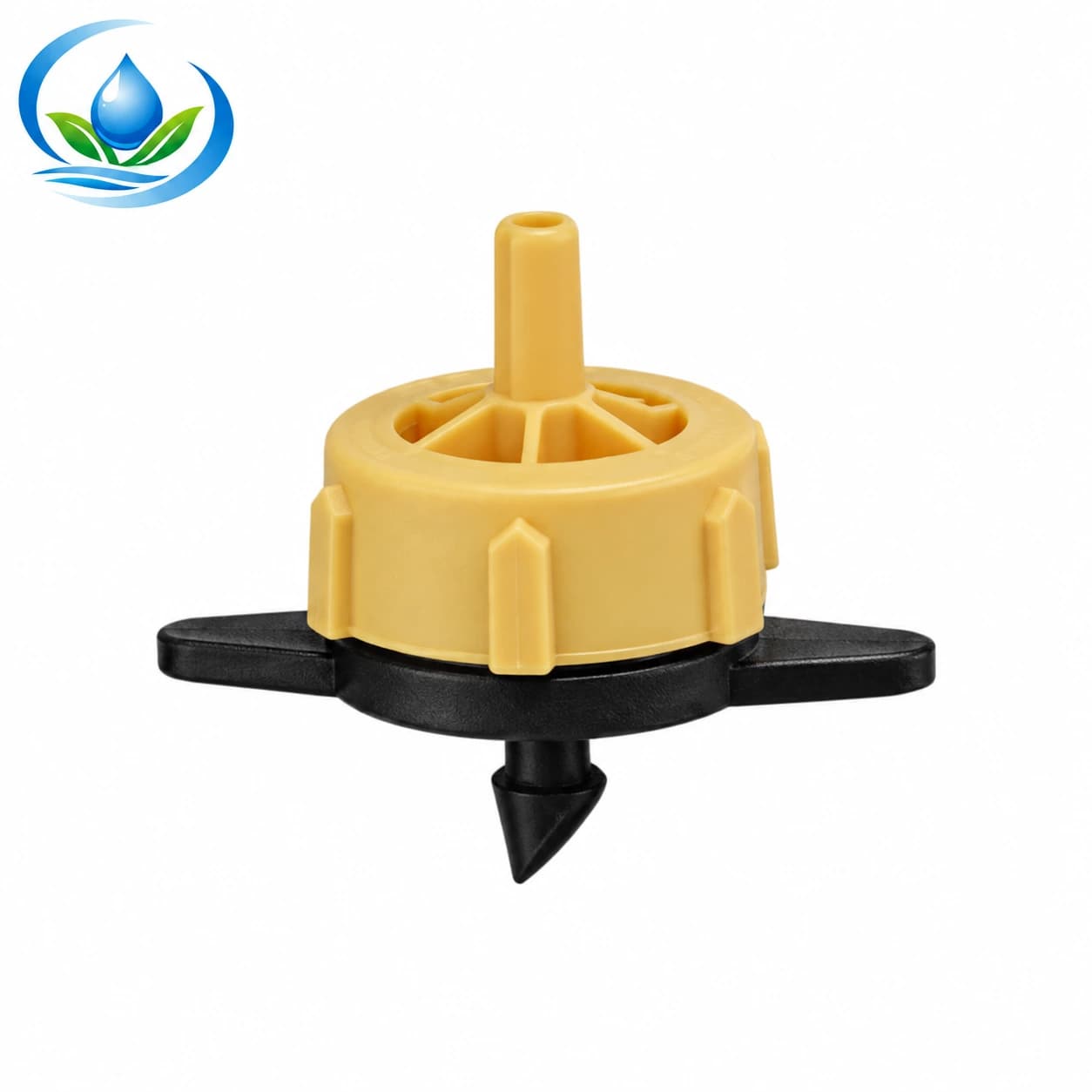
The IrriNex pressure-compensating emitter family lists 2, 4 and 8 L/h choices and a current parent-level operating range of 0.05–0.40 MPa. Verify the exact variant, barb, inlet and outlet arrangement and data before purchase; a family range is not permission to combine specifications from different variants.
Use adjustable emitters for the right reason
An adjustable dripper lets an operator change the outlet opening. It may help during commissioning, with containers of different sizes or where individual plants need observable tuning. The tradeoff is that knob position is not a calibrated flow record. Pressure, debris and manual setting can produce different delivery among outlets.
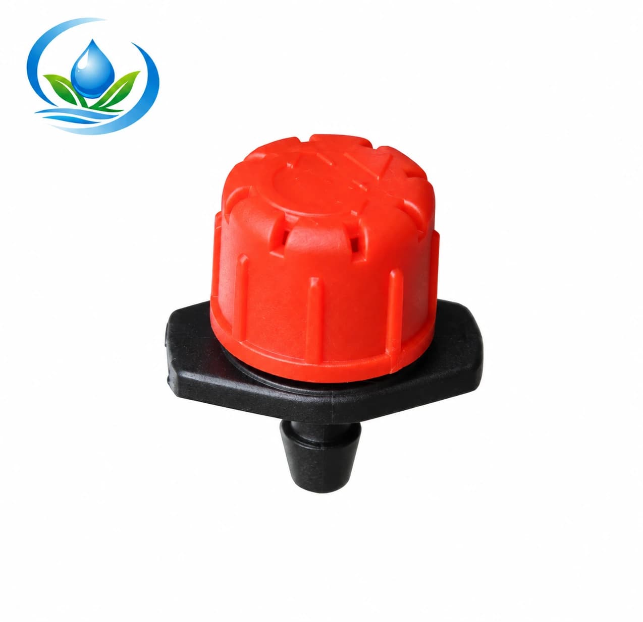
The current adjustable dripper lists a 0–70 L/h option, a 4mm barb and a parent-level 0.10–0.30 MPa range. Confirm the selected variant. Measure several installed units at the intended setting rather than assuming halfway open means half the maximum. Use fixed-flow products when repeatable auditing matters more than individual adjustment.
Compare the three retail routes
| Product route | Useful starting condition | Buyer must verify | Main operating check |
|---|---|---|---|
| Fixed flag emitter | Level, predictable blocks with a selected fixed output | 4, 8 or 16 L/h variant, connection and pressure response | Measure near and far outlet delivery |
| Pressure-compensating emitter | Longer runs or elevation where pressure variation must be controlled | 2, 4 or 8 L/h variant, operating range and barb arrangement | Keep every outlet within the documented pressure window |
| Adjustable dripper | Accessible plants needing field tuning | Adjustment range, barb, pressure range and operator access | Measure and record representative settings |
Price per emitter is only one line in the comparison. Add labour, punch, micro tube, plugs, filtration, flushing and replacement inventory. A cheaper outlet that requires frequent manual correction can cost more to operate; a sophisticated outlet used below its minimum pressure may perform worse than a basic product in a well-designed small zone.
Calculate total sector flow before choosing quantity
For one emitter type, multiply emitter count by nominal flow. A sector with 180 emitters rated at 4 L/h has a planned outlet flow of 720 L/h. When outputs differ, calculate each group separately and add them. Include deliberate future outlets only if the current design will operate them at the same time.
Compare the total with measured source flow, valve capacity, filter range and the allowable flow of the lateral. Use the drip-flow calculation guide to keep units consistent. Leave an evidence-based margin for pressure loss and field variation rather than treating the source's open-flow test as available flow at operating pressure.
Check lateral capacity and pressure at the far end
Flow moving through the lateral decreases after each outlet, but friction and elevation still change pressure along the route. Diameter, length, fittings, inlet pressure, total emitter demand and terrain work together. A catalogue flow rating for one emitter does not establish the maximum number on a line.
Draw each lateral with length, elevation direction, emitter count and output. Measure pressure at the start and near the hydraulically difficult end while all planned outlets run. The drip-pressure guide provides a worksheet. Divide long or heavily loaded routes into zones when the end cannot remain inside the product's range.
Match the barb, opening and micro tube
Terms such as 4mm, 4/6mm or 4/7mm may describe different features: a barb, a tube's inner and outer dimensions, or a marketing family. Confirm actual mating dimensions for the selected product and tube. Do not assume every black micro tube fits every emitter carrying a similar label.
If the emitter inserts into PE pipe, use the hole size and punch specified for that barb. The 4mm emitter punch is a product option only when its prepared opening matches the chosen connector. Test on an offcut. An oversized or torn hole leaks; a makeshift cut can split later under pressure.
When moving the watering point away from the lateral, match the micro distribution tube to both inlet and outlet barbs. Keep the run short, supported and free of kinks. Count one length per remote point plus the correct stake or outlet, rather than assuming the emitter body includes the delivery assembly.
Select filtration from the smallest water path
Point emitters meter through small passages that can be restricted by sediment, organic material or precipitate. Filter selection depends on source water, emitter requirement, total zone flow and the form of contamination. Use the most restrictive relevant component requirement and confirm it for the exact variant.
The irrigation filtration buying guide compares screen, disc, media and hydrocyclone roles. Add pressure-measurement points around the filter and provide a cleaning method. A cleanable emitter can simplify local service, but it does not replace head-unit filtration or line flushing.
Plan flushing and end access
Install a serviceable end or flush point on each lateral. Flush new construction before inserting emitters when the product instructions allow it, because drilling fragments and soil can move toward small passages. During operation, use a flushing interval based on observed water quality, pressure change and material collected at line ends.
Place ends where discharged water and any permitted treatment residue can be managed. Keep a map of flush points so field staff do not leave a cap buried or inaccessible. After service, pressurize the zone and inspect the last outlets before assuming the line is clean.
Calculate an order without guessing
- Operating emitters: planned watering points in each sector.
- Expansion emitters: only the documented near-term plant-growth allowance.
- Service stock: a consistent spare quantity based on field access and lead time.
- Correct punch or insertion tool for the chosen barb.
- Micro tubing and stakes for remote points, measured by route.
- Plugs for test holes, removed emitters and expected layout changes.
- Compatible lateral pipe, start fittings, isolation valves and flush ends.
- Filter elements or service parts appropriate to the selected head unit.
- Pressure gauges or test adapters for the first and far points.
Separate each flow and connection variant into its own line item. Record the product-page URL and the date specifications were checked. Avoid a mixed bin of colour-coded emitters without labels; colour is useful only when the site's variant mapping is documented.
Install point emitters consistently
Lay and pressurize the lateral according to its instructions, mark plant positions and make clean holes with the matched tool. Insert each barb squarely without widening the opening. Respect any flow-direction arrow. Support micro tubing so plant work, machinery or animals do not pull on the lateral.
Place water at the planned active root area, not automatically against the stem. For trees, update placement as the effective root zone expands. Keep devices visible enough to inspect unless the selected product is explicitly rated for the planned installation. Map capped or unused openings so they are not mistaken for failures.
Commission with a measured catch test
- Flush the head unit, submain and laterals in the planned sequence.
- Run the complete zone until pressure stabilizes.
- Measure inlet and far-end pressure.
- Catch delivery from representative near, middle, far, high and low positions for the same timed interval.
- Convert every catch to the same unit per hour.
- Compare results with the selected variant and investigate outliers.
- Record filter condition, pressure, run time and any adjusted outlet position.
For adjustable emitters, repeat after final settings are made. For pressure-compensating units, confirm that the least-pressurized point is still within the documented range. A single sample beside the valve cannot prove performance across a sloped or long block.
Troubleshoot the measured pattern
If near emitters deliver more than far emitters, check pressure difference, total flow, lateral size, zone length and whether the products are truly pressure compensating. If isolated outlets are low, inspect for debris, kinked micro tubing, wrong variant or installation damage. If every outlet is low, inspect the source, valve, filter and inlet pressure before replacing all emitters.
Leaks around punched holes indicate an opening or barb mismatch, a damaged lateral or poor insertion. An adjustable unit that will not repeat may need cleaning or a fixed-flow replacement for easier auditing. Record the symptom and location before changing several variables at once.
Maintain and expand the system deliberately
Walk the zone while it is operating, clean the filter on evidence, flush ends and compare representative catches over time. Replace damaged devices with the same documented variant unless a redesign has been calculated. Keep spare products sealed and labelled by flow and connection.
As plants mature, reassess water volume, wetted area and emitter placement. Adding outlets increases total sector flow and changes pressure. Recalculate before expanding many trees at once, and use the zone-planning guide if the existing valve can no longer support the revised count.
Frequently asked retail questions
Are all drip emitters pressure compensating?
No. Fixed basic, pressure-compensating and adjustable products behave differently. Use the product specification rather than appearance or colour.
Can I mix 2, 4 and 8 L/h emitters on one lateral?
They can be calculated as separate groups, but mixed flows complicate auditing and scheduling. Confirm the total flow, pressure range and plant-water plan before mixing.
How many emitters can one lateral support?
There is no universal count. It depends on diameter, length, inlet pressure, elevation, emitter output, spacing and acceptable pressure variation. Calculate and measure the actual route.
Does pressure compensation fix low pressure?
No. The emitter must first reach its documented operating range. Compensation cannot supply pressure that is missing at the far end.
Should I buy adjustable emitters for every plant?
Only when field adjustment and access are useful. Fixed-flow devices are easier to count and audit when plants share a planned demand.
Use a five-column check before adding to cart
Write one final row for each emitter variant: nominal flow, documented pressure behavior and range, inlet/outlet connection, required filtration and ordered quantity. Add the calculated total zone flow below it. If any cell is unknown, resolve it before checkout.
Compare the 2/4/8 L/h PC family, the adjustable dripper and the 4/8/16 L/h flag emitter. Then add the matched installation and service parts. For a specification that is not shown, send the measurements and selected variant to IrriNex Store support before ordering.
Before you order
Compare this guide with the specifications for your exact product, selected option, water supply and field conditions. Your equipment requirements take priority over a general example.
Compare irrigation products