Irrigation Scheduling: Fit Manual Crop Blocks Into a Real Watering Window
Place measured block runs and manual valve changes on one clock before adding another crop block to a shared supply.
Published by IrriNex Store
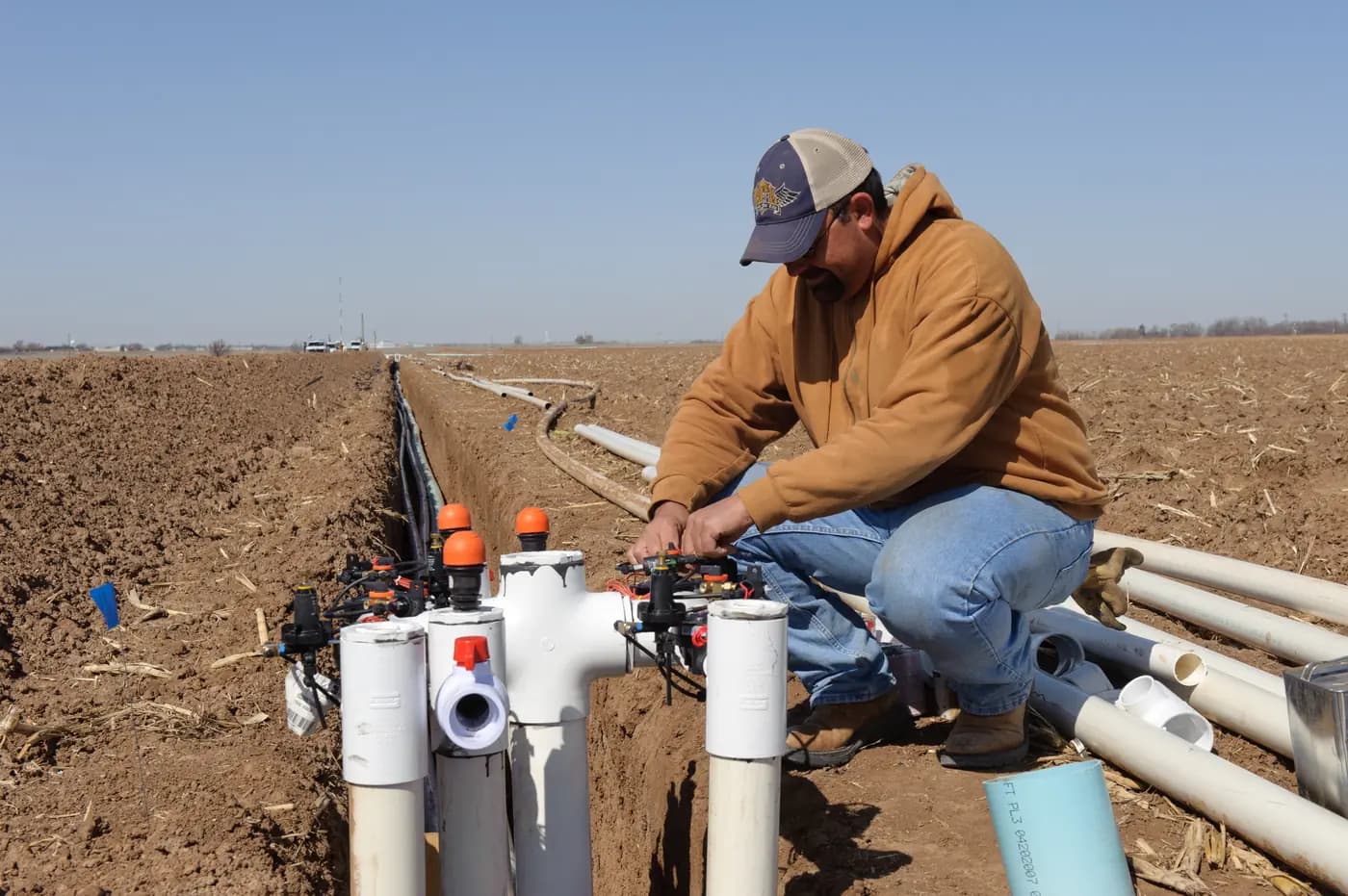
Irrigation scheduling becomes a different problem when one worker must switch several farm blocks through a shared water supply. Each block may already have an approved crop-water target and a workable valve. The missing decision is whether all required runs, travel and changeovers fit the hours when water and staff are actually available. Put those times on a clock before buying another manual valve for a new block. A valve can give that block independent control; it cannot add hours to a short morning window. Put each block's already approved delivery duration and the operator move on the same clock line; another manual valve cannot lengthen a short source window. A manual irrigation block time window includes the approved watering duration plus travel and valve-change time.
Begin with the crop decisions already made from local soil, crop and weather observations. Record the event volume or other delivery target for each named block, the measured delivery rate under its normal operating arrangement, and the earliest and latest permitted operating times. This is a practical shift plan for an existing manually operated system. It does not substitute a clock calculation for deciding how much water a crop needs.
How many manual blocks fit within the actual water window?
Mark the period when the water source can dependably supply the permitted blocks and the person responsible can reach their controls. A well that recovers slowly, shared farm demand, an electricity supply period or a work route can make this window narrower than daylight. Record any fixed time when a block must be off because harvesting, vehicle access or another planned operation starts. A window is an operating constraint to check, not a universal recommendation to irrigate at one hour of the day.
Also mark the controls that cannot safely be operated at the same time. If the hydraulic design allows only one block, the clock must contain the full length of each run in sequence. If some combinations are documented to run together, record those exact combinations and their measured flow and pressure. Do not shorten the proposed schedule by simply drawing overlapping bars for valves whose combined demand has never been checked. The farm zoning guide helps establish which rows belong to each permissible operating group.
Use the same definition of a shift across the plan: source available, block valve correctly set, pressure and delivery stable, and a person able to verify the transition. If the source is available from 06:00 but no one can open the first field valve until 06:25, the usable manual window does not begin at 06:00. Likewise, a worker who must leave for another task before the last block closes cannot assign that block an unattended finish unless an approved control and handover arrangement actually exists.
Separate valve-on minutes from travel and changeover time
Create one row per block: crop and stage, local target for this event, normal open valves, relevant delivery rate, expected run duration, operator and next required check. Keep the target's basis visible. Litres for a whole block cannot be divided by litres per hour from one emitter. A depth over a known area, litres per row and litres per entire block are different quantities. Convert them only when the area, outlet count and measurement boundary are known.
Use the rate observed while that block runs under its normal pressure and with its usual filter and source condition. A meter at a shared head may count a leak, another user or water filling long lines; it does not by itself measure the volume delivered to plants in one selected block. Compare representative near and far outlet observations, or another accepted field delivery method, with the head reading. If the measured rate is unstable, fix the delivery question before promising a finish time. The field-meter reading guide explains why a meter total needs a defined boundary.
When a component change altered outlet flow, recalculate that block's event before placing it on the clock. Keeping the old minutes can deliver a different volume. The changed-emitter runtime worksheet shows the single-block arithmetic. Here that validated duration becomes one input among several shifts; the schedule should not quietly change the crop target to make the columns add up.
Count valve-on time and elapsed clock time separately
For a stable measured block flow, the first arithmetic screen is run time in minutes = intended delivered litres ÷ relevant litres per hour × 60. The result assumes the rate and target describe the same block and that the measured delivery condition is representative. If the line takes time to fill before far outlets deliver, account for that observed behavior in the event measurement or as a separate documented allowance. Do not count it once in the measured event and again as a generic setup penalty.
Valve-on minutes are the periods during which a named block is commanded to receive water. Elapsed clock time starts when the first manual operation begins and ends when the last required check and close are complete. Walking between controls, changing the permitted valve state, waiting for the pressure to settle and checking the first and far rows may occupy time between runs. A crew should measure these tasks on its own route; neither a fixed five-minute changeover nor a percentage added to every event is credible for every farm.
Write each changeover as a separate row with its start and finish. Identify whether the source or pump remains in an approved operating state during that interval. A manual valve is not a pump bypass, and closing the final outlet against a running pump may be outside the equipment procedure. Follow the actual system's shutdown and start sequence rather than inventing a fast transition to improve the spreadsheet. If the changeover is done by two workers, record who does what; do not assume the second worker is available every day.
Try a complete three-block clock example
The following figures are invented to demonstrate the timetable, not crop recommendations or measured IrriNex equipment performance. Assume Block A has an independently established event target of 210 L and a verified delivery rate of 180 L/h: 210 ÷ 180 × 60 = 70 minutes. Block B requires 320 L at 240 L/h, giving 80 minutes. Block C requires 300 L at 200 L/h, giving 90 minutes. Their total valve-on time is 240 minutes. Suppose the farm has observed a 10-minute A-to-B changeover and a 15-minute B-to-C changeover. Those 25 minutes are illustrative route and operational inputs, not a standard interval.
| Clock step | Illustrative time | Elapsed minutes | What the operator verifies |
|---|---|---|---|
| Block A | 06:00–07:10 | 70 | Selected A route and expected delivery |
| Change A to B | 07:10–07:20 | 10 | Approved valve and source sequence |
| Block B | 07:20–08:40 | 80 | Selected B route and expected delivery |
| Change B to C | 08:40–08:55 | 15 | Approved valve and source sequence |
| Block C | 08:55–10:25 | 90 | Selected C route and final close |
If the actual permitted window is 06:00–10:30, this plan uses 265 of its 270 minutes and leaves only five minutes of clock space. That is an observation, not an endorsement of five minutes as a safe margin. A late start, a clogged outlet, an unexpected source change or a delayed worker could push the last block beyond the boundary. Set any operating allowance from the farm's own reliability history and the consequence of a missed finish; do not borrow one universal buffer percentage.
Now suppose a fourth block is proposed. Its locally determined target is 150 L, and a representative operating test supports 150 L/h, so it needs 60 valve-on minutes. If the C-to-D transition has been measured as 12 minutes, the new plan would require 265 + 12 + 60 = 337 minutes from 06:00, ending at 11:37. That is 67 minutes beyond 10:30. Buying a new branch valve makes D controllable, but it cannot make a 337-minute sequence occupy 270 minutes. Check another permitted watering window, a separately managed day if the crop plan allows it, a documented source or zoning redesign, or an approved operating combination. Do not erase 67 minutes by arbitrarily reducing one block's crop-water target.
Test the tightest part of the day against the real source
The example's rate for each block is meaningful only while the source can sustain that block's required pressure and flow. A source that starts strongly and weakens as a tank level falls may change the duration of a later shift. A source shared with washing, livestock or another field can vary with concurrent use. Record which users were active during each rate test and repeat a relevant test under the weaker credible condition. A static pressure reading before the shift and an open-hose bucket trial cannot validate a closed field's delivered rate at its working pressure.
Where the rate changes during an event, a single litres-per-hour value may be a poor time predictor. Use the farm's accepted delivery record over the full event, or divide it into measured intervals under defined conditions. Note whether the first and last rows remain within the block's approved delivery limits. If the planned last block regularly starts after the tank has fallen, test that position in the sequence instead of applying its early-morning flow to the late slot. Keep any pump and valve duty within the selected equipment's documented operating range.
If the timetable appears impossible only on certain days, preserve the reason: source restriction, pump fault, another user, field access or a crop target change. Those lead to different remedies. A larger valve does not increase the water available from a falling source. A timer could automate a permitted transition but does not create water capacity, eliminate field inspection or approve an untested overlap. Make the time problem visible before choosing hardware.
Use manual valves for the actual line they control
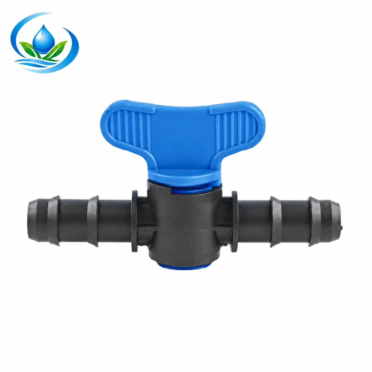
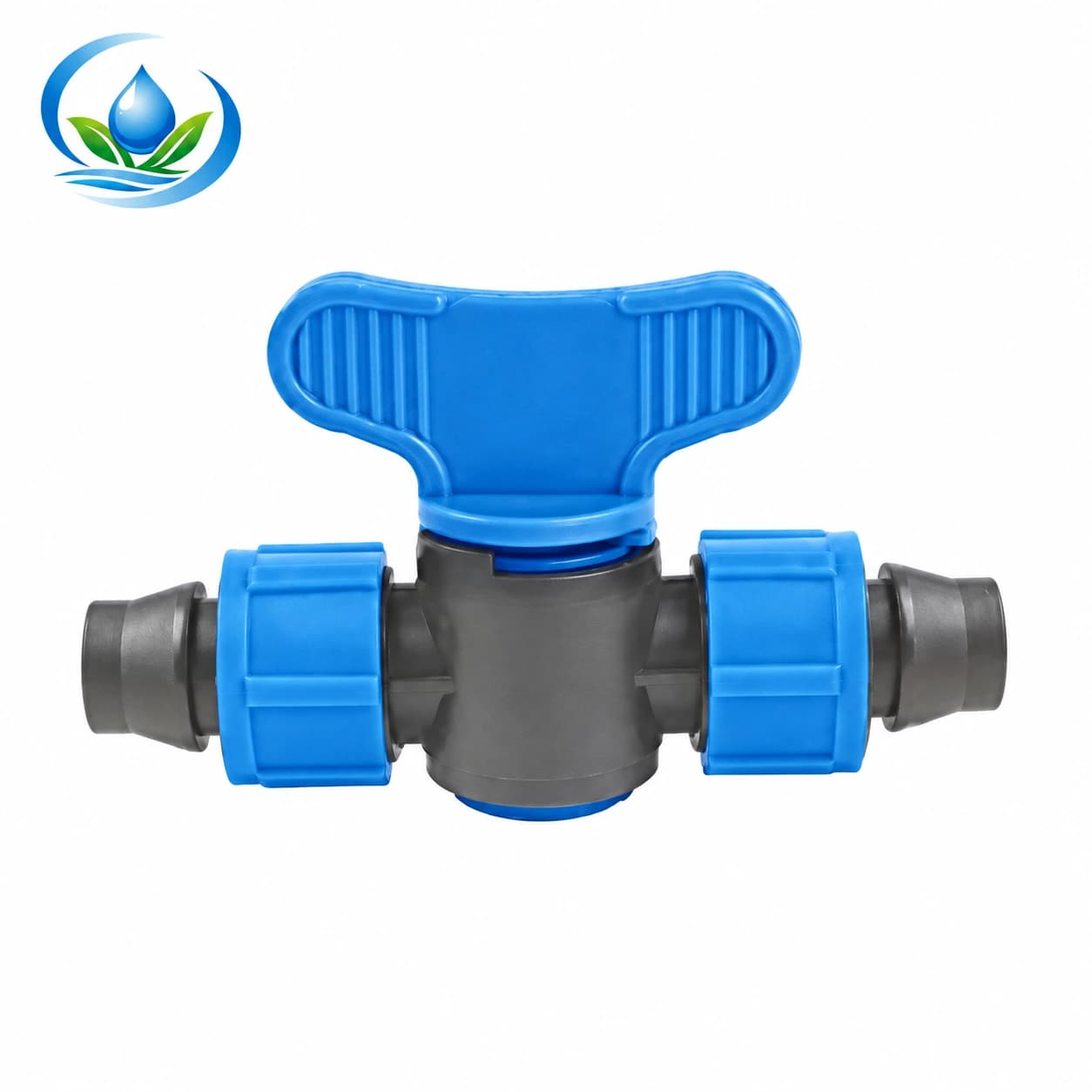
A named manual control is useful when a worker must isolate one crop row or segment without disturbing another. Its physical job still depends on the connection in front of it. The blue-handle Maxi Valve includes the V16A1 nominal 16 mm barbed straight-through option. The V161 lock-tape coupler valve is listed as a 16 × 16 mm tape-to-tape connection. They are different connection routes; the shared number 16 does not make them substitutes for one another.
Draw the pipe or tape on both sides of a proposed control. A tape-to-tape coupler in one run can interrupt a downstream segment of that run; it does not independently switch a separate parallel row that joins at the header. A barbed valve is not automatically a documented fit for every nominally 16 mm round tube or tape wall. Confirm the exact selected variant, mating material and dimensions, pressure suitability, installation method and sale unit before ordering. If the correct valve position is a header branch rather than an in-line segment, choose a documented connection for that location instead of moving the valve symbol on the clock sheet.
Keep the operator's path in mind. A valve hidden under mulch or behind a harvested crop may add unplanned changeover time and become hard to check. Label each reachable control with the same block name used on the timetable. Record the normal and temporary states without presenting a handle position as a measured flow setting. The staggered vegetable-row guide helps identify which planted rows need independent decisions; the clock sheet then shows when the approved groups can actually run.
Retain an auditable handover for the next shift
Give the crew a one-page schedule showing date, source condition, named blocks, crop-approved targets, measured rate basis, valve-on intervals, changeovers, responsible person and latest permissible finish. Leave a column for actual opening, stable delivery and closing times. If a worker arrives late, the sheet should show which remaining commitments need a fresh crop decision, rather than inviting an unnoticed shorter event. The field-crew handover guide helps keep part identity and control labels with that record.
Recheck the plan after rain, a changed crop stage, a replaced outlet, a cleaned filter, a repaired line or a different water source. The after-rain field check establishes whether a particular block's next event is still called for. If an additional bed is installed, the new-bed supply comparison checks its old-only and combined hydraulic cases; only then should its verified standalone or permitted combined run be placed on the timetable.
Before paying for another manual valve, follow one representative shift with the present controls. Record actual transition times, normal source behavior and whether the last block closes inside the allowed window while receiving its intended water. If the sequence fits, buy only the correctly matched control parts needed to make it repeatable and check current price, pack, availability and delivery for those exact options. If it does not fit, keep the shortfall in minutes on the order brief. That number tells the farm what must change before an additional crop block can be promised a place in the rotation.
Before you order
Compare this guide with the specifications for your exact product, selected option, water supply and field conditions. Your equipment requirements take priority over a general example.
Compare irrigation products