Irrigation System Valve: Manual, Solar Remote or Electric for a Farm Zone?
Match a farm zone's flow, pipe interfaces and operating routine before choosing a manual, solar remote or electric diaphragm valve.
Published by IrriNex Store
An irrigation system valve for a farm zone does two jobs that should be chosen separately: it fits the water line at the correct operating flow and pressure, and it opens or closes by a method the farm can reliably use. A hand-operated valve needs a person at the field. A solar remote valve needs an approved power and communication arrangement. An electric diaphragm valve needs a compatible controller and electrical circuit as well as suitable water conditions. None of those words proves that a particular product fits the pipe already installed. Start with the zone and its normal operating procedure, then compare actuation routes and exact valve options.
This guide compares a complete zone-control decision. If the question is only which two fittings match a local manual shutoff, use the manual valve connection guide. If a valve is already leaking or refusing to close, use the fault diagnosis guide before replacing it. A new actuator cannot repair an undersized zone, a mismatched thread or a sediment problem by itself.
Define the zone the valve will actually control
Mark the source, filter, pressure control, proposed valve position, header, crop rows and farthest outlet on a drawing. List the crops and outlets that operate when that one valve is open, their simultaneous flow, working-pressure requirements and any permitted overlap with another zone. The farm zoning guide establishes that operating group. Do not choose a valve from field area or pipe colour alone. A one-hectare block of tape and a one-hectare block of overhead heads can ask very different things of the same water source.
State the control task in one sentence: “This valve starts and stops the named north vegetable block while the filter and upstream main remain in service,” for example. Then identify what must happen when the valve is closed: should another block run, should a pump stop, or does the source have a documented bypass? Closing the last outlet against equipment that requires flow may be unacceptable. The valve's off command is one step in the approved source sequence, not a universal pump protection device.
Record the smallest, normal and largest allowed flow cases. A zone may shrink after harvest; a flushing state may differ from normal irrigation. Check these cases against the exact candidate valve's permitted flow and pressure data, as well as the filter and regulator. Measure pressure with the intended group operating, not only static pressure with everything shut. A nominal pipe size alone says little about loss through the valve at the intended flow.
Choose manual operation when the field routine supports it
A manual valve is straightforward where an operator can reach the control, see the relevant field and fit all necessary runs within the available water window. It is useful for an isolated branch, a service boundary or a small block whose staff already visit it. It does not close at a scheduled minute when nobody is present. Put travel, opening, flow-stabilization check and final close on the work timetable; the manual block scheduling guide shows why valve-on minutes and elapsed shift time differ.
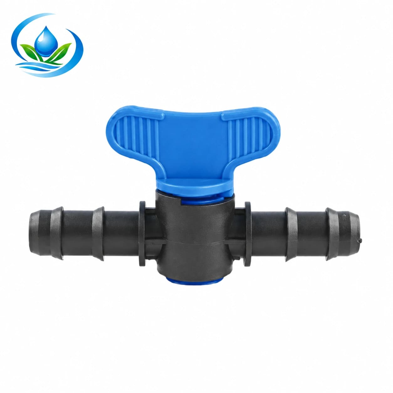
The published blue-handle Maxi Valve has listed nominal 16 mm and 20 mm options. These may be candidates for appropriate small tubing or row branches after exact fit and operating limits are verified. Their listed sizes do not make this product a default manifold valve for a large farm zone. If the proposed control point is on a larger mainline, obtain a genuinely sized manual valve and its connection data; do not neck down an established pipe to a small branch fitting simply to use a familiar handle.
Mark the handle where crop growth will not hide it and where the operator can stand safely. Keep the expected normal state on the field map. If the route requires one worker to run between distant valves, calculate actual transition time before deciding that manual control is cheaper over the season. The decision may still favour a hand valve, but the evidence is the reachable location and repeatable shift, not the absence of an electrical price on a product page.
Choose remote solar operation only with a workable signal and power plan
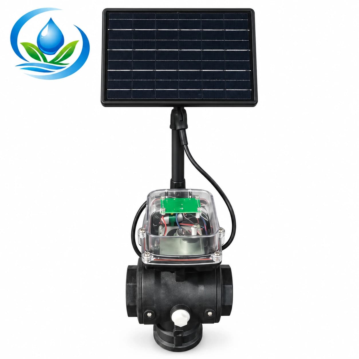
A remote-operated ball valve can reduce routine trips to an outlying zone, particularly when the field lacks a convenient wired controller. The solar remote irrigation ball valve family lists DN32–DN110 sizes and communication options described as 4G, LoRa or RS485. Those are family data, not proof that every listed size includes every communication module or that a field has usable signal. Online ordering is not currently available for this model. Confirm the exact option, supplied actuator and panel, energy storage, communications hardware, control service and availability.
Walk to the proposed installation location with the person who will operate it. Check where the solar panel can remain exposed through crop growth and seasons, how it is secured and serviced, and whether the intended communication route reaches the site reliably. LoRa requires a suitable gateway arrangement; cellular operation depends on actual network service; RS485 requires a suitable wired connection. Do not select a protocol by name alone. Ask how the exact controller reports a command, whether it confirms actual valve position, and what happens after weak battery, lost signal or an interrupted operation. A phone displaying “sent” is not the same as measured water at the far rows.
Document an approved local way to isolate and test the zone if remote control is unavailable. Confirm the exact unit's manual override, safe state on power loss and position feedback from its own instructions; do not assume all motorized valves fail closed. Keep electrical enclosures, cable routes and service access appropriate to the installation location. Remote operation may solve labour travel, but it adds maintenance of power, communications and records. It should be chosen only when the complete operating chain is supportable.
Choose an electric diaphragm valve with a compatible controller
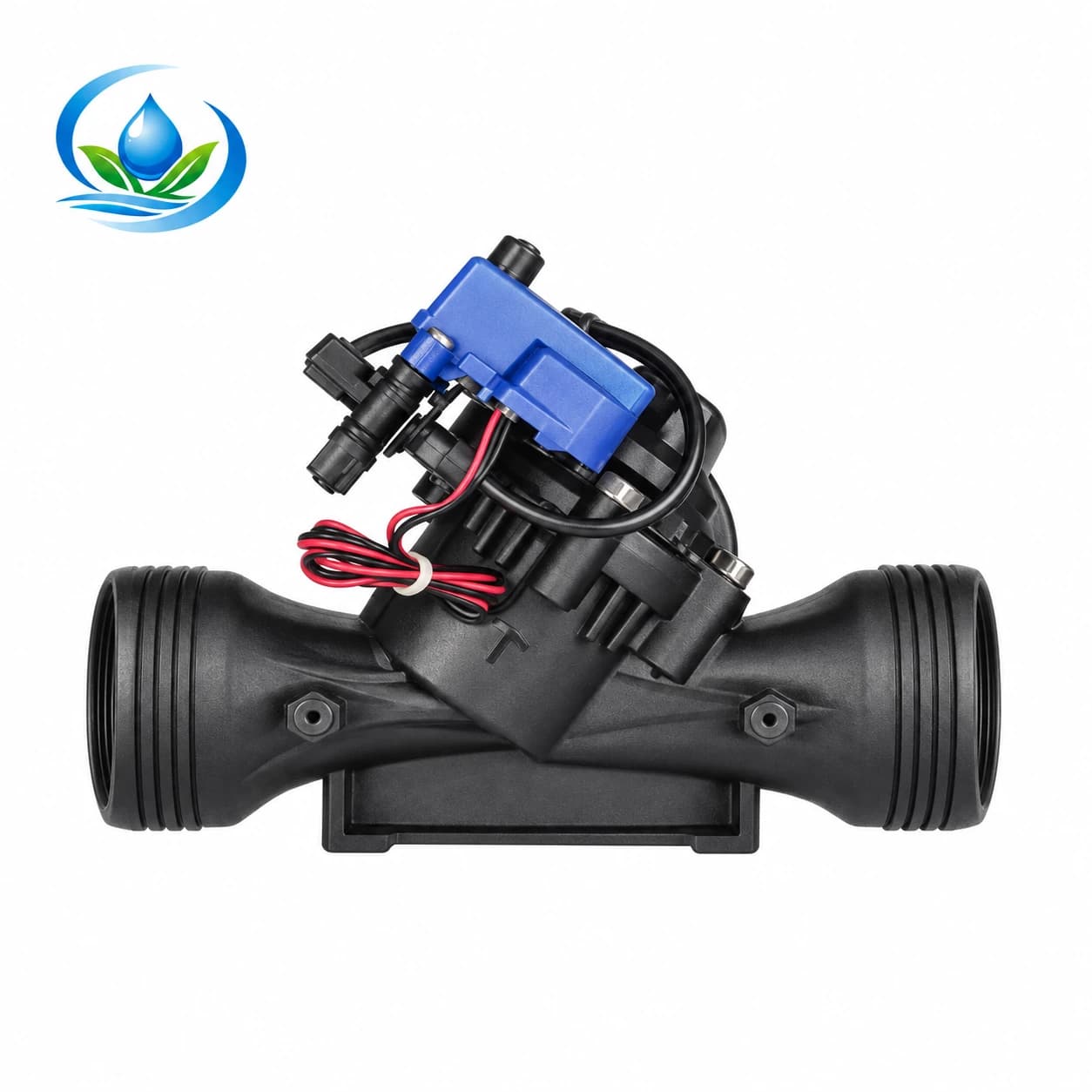
An electric valve can switch a scheduled zone from a controller where a suitable power and wiring path already exists or is planned. The published electric diaphragm irrigation solenoid valve family lists threaded or flanged connections by size and a family operating-pressure range. The specific option, actuation voltage, coil type, flow envelope, connection standard, required filtration and controller compatibility must be checked before selecting it. A label saying “electric” does not tell you whether it is compatible with a particular AC station, DC latching output or two-wire decoder.
Draw the control path as well as the water path: controller output, cable route, junctions, solenoid, valve body and the operator's way to verify actual flow. A farm may prefer wired electric control when the valve is near a reliable controller or when several zones use one established system. The design must cover wire length and protection, serviceable connections, weather exposure and a documented manual operation method. Manufacturer instructions for other brands can illustrate these questions, but their wiring diagram cannot be copied onto the Store valve without a matching specification.
Diaphragm valves also depend on appropriate hydraulic conditions. Check whether the exact option requires a minimum pressure differential, the permitted flow, and water quality for its pilot passages. A valve that will not close may have debris or a control fault rather than being the wrong diameter. Do not call it a pressure regulator unless the selected assembly includes a documented regulating function. The University of Minnesota Extension's specialty-crop irrigation guide explains why filtration and zone pressure control remain part of the farm system; choosing automation does not remove either task.
Compare the entire installed path, not three catalogue photographs
Make three columns headed manual, solar remote and wired electric. Under each, write the exact candidate model, inlet and outlet connection, permitted flow at operating pressure, actuator requirements, normal operating action, loss-of-power or signal behavior, manual intervention, service access and current purchasing route. Leave a blank where a product page does not provide an answer. A blank is a question for the exact product documentation, not permission to insert a value from a similar-looking valve.
Trace connection standards carefully. The small Maxi option uses its own nominal branch connection; the remote family uses DN labels; electric options may be threaded or flanged. These labels refer to different physical measurements. Match both existing pipe ends and any required adapter, gasket, support or union. If the old line is cut only after the decision, measure sound pipe and leave enough straight, accessible length for the prescribed assembly. The Philmac installation resource for its own metric fittings illustrates why insertion and support method belong to the exact fitting; it does not approve a cross-brand joint here.
Compare the installed cost and work, not merely a displayed unit price. Manual control has operator time; remote control may need panel, gateway or service; electric control may need cable, controller stations and protected joints. Filtration, pressure measurement, upstream isolation and access remain relevant for all three. The two automated Store product records are not currently marked directly purchasable, and a zero price for a variant is not a free offer. Confirm exact option, contents, availability and current quotation before basing a planting schedule on delivery.
Test one complete zone transition before repeating the choice
With the approved design and qualified installation procedure, test one representative valve and operating group. Before the first open, verify that the intended upstream and downstream boundaries are known, joints are supported, filters are ready and the control path responds. Bring water on through the equipment's startup sequence, allow pressure and flow to stabilize, then observe for joint leaks and correct downstream delivery. The command or handle position alone is not proof that every row receives water.
Record head pressure and flow, an appropriate downstream pressure, and representative outlet response. Operate the normal close and verify that the zone stops as expected without leaving another group starved or the source in an unsupported state. For remote or electric control, repeat under its intended controller sequence and check its confirmation, alarms or manual access according to the exact model. Plan how an operator will recognize a command that did not result in water movement. Do not use a trial on one small branch to certify all DN sizes or a different valve actuator.
Ask what happens after a power interruption, communication loss, clogged filter, harvested rows or a person using a local override. Only test such cases by the equipment and farm procedures; do not improvise a failure under live pressure. A successful first cycle should leave a written valve state, zone name, model, control method, pressure observations and person responsible for reopening or investigating it. That record prevents an automated schedule from concealing a manually left-closed valve.
Make the purchase decision from a one-page zone record
Record crop block, allowed simultaneous zones, operating flow and pressure, the two pipe interfaces, accessible valve site, chosen method, power or signal path, expected fail response and how field staff will verify delivery. Add the exact product option and the parts that make it installable. If labour and travel are the binding problem and a documented remote system is supportable, remote control may be justified. If a controller and protected wiring already serve neighbouring zones, an electric diaphragm option may be worth comparing. If visits are routine and the water window fits, a correctly sized manual valve may be enough.
Do not use a new valve purchase to hide a hydraulic or crop-scheduling problem. One controller cannot make incompatible crops require the same watering duration, and a larger connection cannot create missing pump capacity. For a line-work stop, follow the safe work-boundary guide; normal zone control is not automatically verified isolation for opening a pressurized pipe. When the chosen option's interfaces and control behaviour are documented and the full transition has been tested, the farm can order and operate the valve for the actual zone rather than for an attractive control label.
Before you order
Compare this guide with the specifications for your exact product, selected option, water supply and field conditions. Your equipment requirements take priority over a general example.
Compare irrigation products