Agricultural Irrigation Hose: Move a Layflat Header Between Crop Blocks
Move an existing layflat header from block A to B by comparing old outlets with new rows, draining safely, checking damage and connections, then testing the new group.
Published by IrriNex Store
An agricultural irrigation hose already serving crop block A may be useful in block B when the crop moves during the season. The decision is not simply whether the layflat header reaches the second field. Its existing outlets must meet the new row positions, its connections must still be sound, and the line must be isolated, drained and handled under the hose maker’s instructions before it moves. Map those facts before buying another hose or trying to reuse every old opening. Layflat hose outlet alignment matters in block B, because a hose that reaches the new field may still put water beside rather than at its crop rows.
This guide follows one identified above-ground layflat header through a block-to-block change. It starts with a record of what works in A, compares the outlet sequence with the rows in B, then turns the mismatch and condition findings into a reuse, adjustment or replacement list. It does not assume that an unused opening can be sealed with any plug, that an old coupling fits a different hose wall, or that the same operating group will deliver water after the route changes.
Check block B rows against existing layflat hose outlets
Before the final run in A, make a simple drawing from the supply end to the closed or serviced end. Number each installed offtake in order and mark the row it actually feeds. Include the connection that joins the header to the supply, any mid-line joins, local valves and the end arrangement. Photograph both hose ends, a representative offtake, the hose label and any model markings on retained fittings. A photograph of a coil after removal will not reveal which side originally faced the supply.
Observe the existing group under normal safe operating conditions and note leaks, unevenly fed rows, visible twists, heavy contact points and any branch under tension. Mark suspected damage on the drawing and on a tag near the section, without touching a pressurized line. A wet patch at a connection should be located before removal so it is not mistaken later for damage caused by the move. The field leak-location guide helps distinguish hose-wall leaks from fitting and downstream faults.
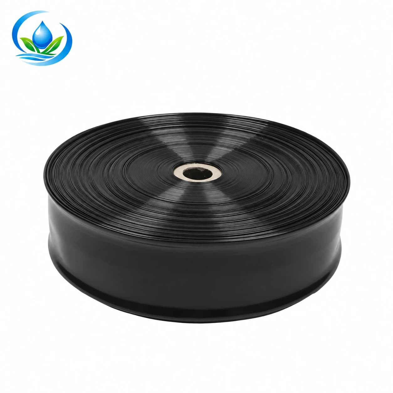
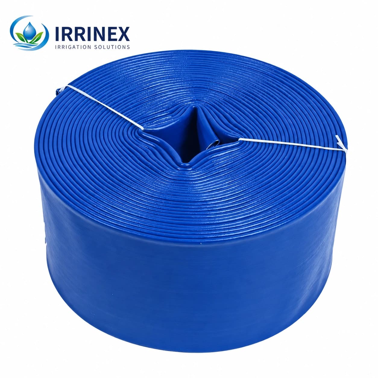
Check the actual hose identity against its label and purchase record. The PE layflat hose listing and PVC layflat hose listing identify separate product families. Colour alone cannot tell you which one is installed, what its allowable pressure is, or how a retained fitting should be removed. If the label has gone, confirm the material, exact hose specification and connection method with the supplier or manufacturer before reuse.
Inspect and drain the layflat header before moving it
Walk the new block with its actual planted rows, access lane and supply point in view. Mark where each row begins and which rows require an active header connection. Give B its own row numbers rather than assuming that outlet A1 will automatically become row B1. If the new header enters from the opposite end, reverse the old outlet order on the comparison sheet. This simple orientation check can expose a mismatch before the heavy work begins.
Set the old outlet positions against B’s measured row positions. Mark each old opening as aligned, potentially usable only with an approved branch arrangement, unused, or damaged. An outlet that falls between rows is not made suitable by stretching its connected lateral across a working path. An unused opening requires a closure explicitly approved for that exact hose and opening, or a different sound section; do not invent a cap because a photographed fitting looks similar.
Consider the operating group as well as the physical locations. Block B may have a different number of simultaneous rows, lateral lengths or outlet devices. Count what will actually run together and compare it with the water source, valve group and known hose rating before reconnecting. The crop-block zoning guide and flow-rate purchasing guide help organize that operating record. They do not establish that an existing header has enough capacity for B merely because it served A.
Choose reuse, adjustment or replacement for each section
Compare the maps in short sections between identifiable joints or boundaries. Reuse a sound length when its confirmed hose construction, connection arrangement and installed openings suit B without forcing branches into new positions. Adjustment may mean changing the route, using a different existing supply end where the maker permits it, or replacing a branch assembly with a compatible one. It does not mean cutting a new hole next to a damaged old one before its seal and spacing have been evaluated.
Mark a section for replacement when the usable length will not reach the approved connection, existing outlets cannot be safely used or closed, or inspection finds damage outside the maker’s reuse criteria. Keep those reasons distinct. A sound length with an outlet pattern for the wrong rows is a geometry problem; a length with splits or permanently flattened folds is a condition problem. Buying a stronger-looking hose does not resolve the location of old openings, and preserving an old outlet does not restore damaged wall.
The layflat row-outlet guide covers fitting selection and a first trial for a newly assembled header. This move begins with already punched positions. Only if B needs a new approved outlet should you use the exact hose and offtake instructions to decide whether another opening is allowed and which tool or seal it requires. Follow the instructions supplied for that hose and outlet; factory-spaced outlets belong to their own hose system.
Shut down, release pressure and drain by the approved route
Use the dependable upstream isolation for block A, stop automatic or pump starts according to the site procedure and verify that pressure has been released before loosening any connection. If the selected valve still passes water, resolve that fault before disassembly; the valve not closing guide helps separate valve leakage from water left downstream. Plan where retained water will leave the hose using the installed equipment’s drain or end-service instructions. A layflat line can appear flat in one place while low portions still contain water. Do not lift or coil a water-filled section to make drainage faster, and do not use compressed air without an exact approved procedure.
Keep workers and equipment away from open hose ends and retained water as the approved drain runs. When flow has stopped, confirm the line is safe to disconnect according to the site procedure rather than relying on elapsed time or the appearance of one flat section. No single drain time applies to every route, slope, connection and hose length. If a low point cannot be drained safely with the available arrangement, stop and use the manufacturer’s or site operator’s method.
Disconnect branches and retained joints in the order specified for the assembly. Support the weight of fittings so it does not pull on a hose wall, and keep an inventory of what came off each end. Do not tow the line with a vehicle, drag it by an attached branch or coupling, drive over it, fold it to stop the water, or treat a fitting as a lifting handle. Use the handling equipment, reel or team method suitable for the actual hose and its documented load.
Label both ends and protect the retained fittings
Attach a durable label to the original supply end and a different one to the former downstream end. Record which end may become the supply in B after the route review; do not assume a reversal is harmless to every included fitting. Give each removed coupling, clamp, seal or branch its code and former position on the map. Keep pieces that belong together grouped, and keep damaged or unidentified parts in a separate container so they cannot be reinstalled as “available spares.”
Photograph the mating surfaces before cleaning away all orientation clues. Look for a distorted hose mouth, stretched connection area, worn gripping surface, missing seal or damaged clamp. Follow the exact fitting’s removal and care instructions. A technique for a small barbed lateral, a camlock system or another manufacturer’s reinforced sub-main is not automatically suitable for this layflat connection. Do not heat, twist or cut around a part unless the chosen product’s procedure calls for it.
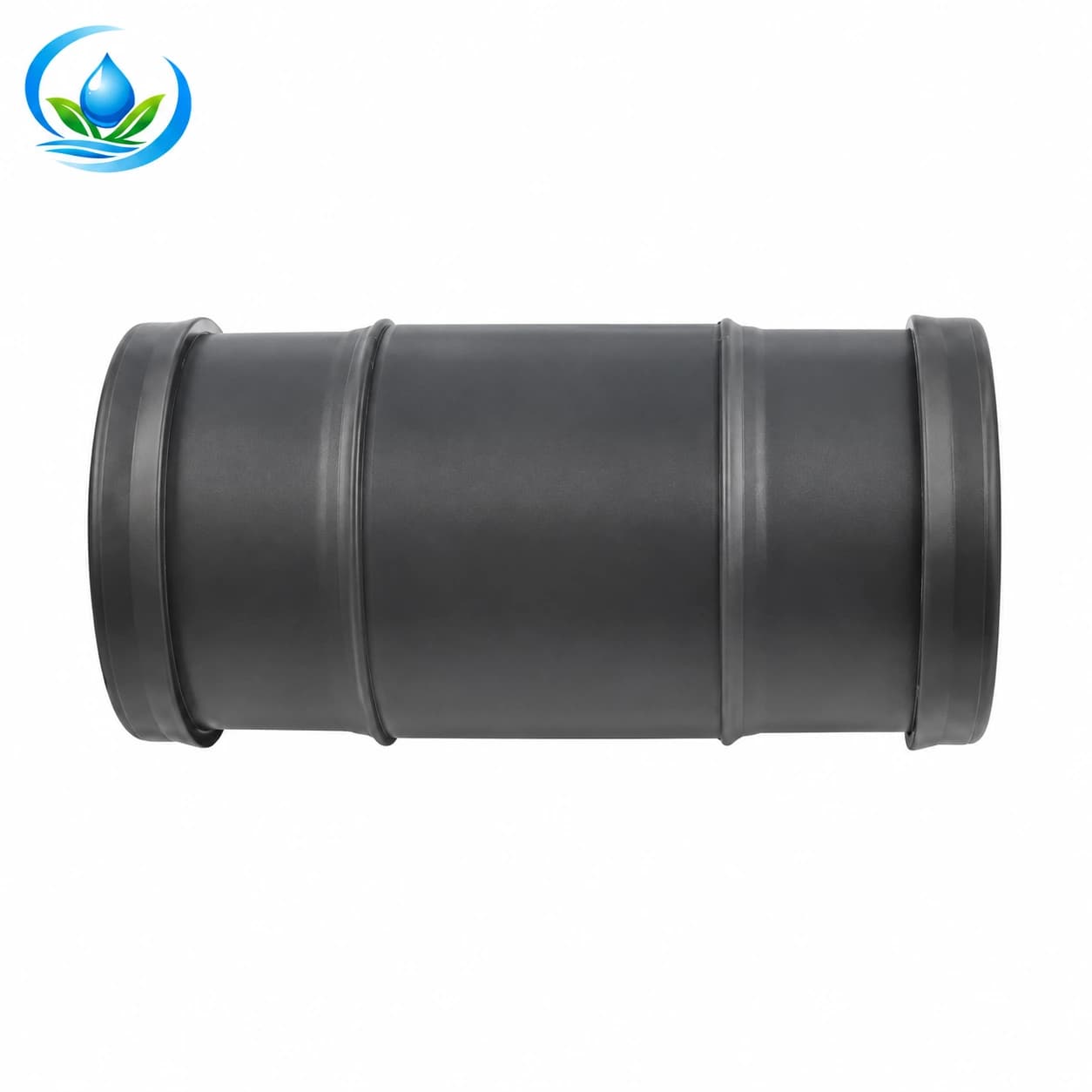
The hose coupling page lists 7900-series sizes including 790032 at 32 mm and larger separate options. It identifies a coupling family; it does not prove that a 7900 item is a quick-release camlock or fits either layflat hose merely because nominal sizes coincide. Record the installed hose’s actual interface, wall and retention method, then verify the exact mating option before putting a coupling into the B parts order.
Inspect the length while it is still identifiable
Move along the drained header section by section and record abrasions, cuts, punctures, a permanently flattened fold, pulled offtakes and stressed regions close to fittings. Note where each defect sits relative to the labelled supply end and an outlet number. A mark on the outer roll is useful only if the associated section can still be located after it is laid out in B. Remove soil gently enough to see the wall without hiding a tear under new damage.
Compare any suspect area with the exact hose maker’s inspection and rejection criteria. A fold that opens when handled is not necessarily restored to its original strength; a scuff is not automatically a leak. Use that hose’s stated limits for bending, handling and operating conditions when judging the section. If an area fails the applicable inspection, set it aside and revise the B map using only sound length rather than guessing that the next irrigation run will “round it out.”
Separate a hose-wall fault from a defective retained joint. A replacement section may still need a correctly matched connector and accessible service space at each end; a new coupling alone cannot repair a long damaged wall. Conversely, a sound hose can leak at a seal that has shifted or deteriorated. Photograph the evidence and take exact component codes to the purchase page. The leak-location guide remains useful at the first B test if a wet point reappears.
Place the accepted header in block B
Use the B map to set the accepted length down with the intended inlet and outlet sequence facing the right rows. Route it clear of the crop work that will follow: cultivation, harvest access, footpaths and sharp fixed edges. Keep connections visible and reachable. Do not put an existing branch under tension to compensate for an outlet that misses its new row. If a protected crossing or a different route is needed, resolve that before reconnecting the branch.
Inspect the new supply connection and each reattached branch with the line still isolated. Compare the old and new mating interfaces rather than relying on nominal size alone. A different pump outlet or header joint in B may require a different approved connector, seal or retention method. Preserve the fitting’s installation instructions and rating alongside the hose identity; a coupling’s available size list is not a pressure or pull-load approval for every hose construction.
Where an old opening has no assigned B row, use only a closure method specified for that hose and installed opening. If none is confirmed, keep the section out of the accepted run and choose a sound replacement or a revised position. Do not leave an old branch loose in the soil, depend on a closed valve as the sole seal for a damaged opening, or bury a questionable outlet under the crop. The goal is a new configuration whose active and inactive connections are both identifiable.
Restart and compare the new operating pattern
Return the group to service using the equipment’s approved sequence and within the verified limits of the actual hose and fittings. Watch the inlet, every retained join, the formerly repaired or suspect places and the end arrangement while they remain accessible. Look for leaks, shifting, renewed folding or strain as the flexible header fills. If a problem appears, isolate and release pressure before adjusting a connection or moving the line.
Check more than a dry connection. Observe the active B rows during a comparable operating period and note whether the farther rows receive water while nearer connections remain sound. If the source, number of simultaneous rows or lateral lengths differ from A, the old run time is not proof of equal delivery. Record pressure at the measurement points available to the system and use the selected hose’s confirmed operating limits and the installed outlets’ specifications for the demand check.
Keep a short B acceptance record: hose identity, inlet direction, accepted section lengths, active outlet numbers, approved treatment of unused openings, fitting codes, and observations from the first run. Revisit the accessible connections after nearby field work changes the traffic or support around them. That record makes the next move a decision about known geometry and condition, rather than a search through anonymous coils.
Buy only the missing pieces for the accepted move
Make three groups on the purchase list: identified parts to reuse, items requiring exact compatibility confirmation, and items to replace. For hose, note the accepted material and construction, measured sound length, confirmed bore and working limits, and the additional length that B actually needs. For a coupling, record both mating ends and the installed retention method. Keep branch and closure questions tied to their specific outlet numbers so the order does not conceal an unresolved old hole.
Check the selected PE or PVC product page for the current option, displayed price, sale unit, availability, delivery and purchase path. Use the coupling listing for the exact listed size only after the interface is confirmed. If a needed hose option or mating detail has no purchase choice shown, send the Store the old label, end photographs, measurements and B route record for an availability or fit answer. Confirm the specifications and order status of the actual option selected for B.
Finish by reconciling the B row map with the retained and purchased pieces. A section reused at the correct openings, a verified connection and a successful first operating check are more useful than a long generic hose list. Keep the old A map alongside B’s accepted configuration so future field work can distinguish openings that moved, closures that were approved and sections that were rejected.
Before you order
Compare this guide with the specifications for your exact product, selected option, water supply and field conditions. Your equipment requirements take priority over a general example.
Compare irrigation products