Venturi Fertilizer Injector Not Drawing? Check the Bypass Before Buying Parts
Compare the last successful operating state with today's bypass, record pressures and inspect the suction route after safe shutdown before choosing repair parts.
Published by IrriNex Store
A venturi fertilizer injector that worked last week but no longer draws needs a comparison of operating conditions before it needs a new body. Identify the last successful irrigation zone, the bypass arrangement and any maintenance since that run. Then prepare a clean-water investigation using the shutdown, pressure-release and restart procedures for the actual equipment. A changed valve route, a different downstream demand or a damaged suction connection can produce similar symptoms. A Venturi bypass pressure check belongs to the approved water-only run, before replacement parts are selected.
Begin with the existing installation and its records. Preserve the equipment identity, normal control positions and source-protection arrangement while you find what changed. The useful outcome is a documented cause or a focused support request that identifies the correct repair. Replacing an injector with the same connection size does not resolve an unsuitable operating condition.
When did the Venturi injector last draw stock correctly?
Write whether the injector draws nothing, starts and stops, draws visibly less, or allows an unexpected change in the stock-container level. Add when the behavior first appeared and whether it happens in every irrigation group. These observations help separate a consistent fault from a condition that follows one particular zone or operating sequence. Stop fertilizer application while delivery is uncertain; extending the run does not establish the missing nutrient amount.
Retrieve the last useful record, even if it is only a dated photograph and the operator's notes. Identify the active outlets, pump mode, source-water condition, filter service state, container position and documented valve settings. Compare those facts with today's arrangement. Mark an unknown as unknown instead of assuming the installation has remained unchanged since commissioning.
Ask what happened between the two runs: filter cleaning, a repaired mainline, changed irrigation groups, a replaced pickup tube, a moved container, frost exposure or work on the bypass. Record events without immediately blaming them. A new hose and a new zone may have been introduced together; changing both again would make the next result difficult to interpret.
Which bypass route feeds the injector during a water-only check?
Use the manufacturer's shutdown and service instructions for the complete station. Stop the pump, prevent automatic restarting, isolate every relevant pressure source and release retained pressure through the designed provisions. Confirm safe depressurization as the procedure requires before loosening a union, opening a strainer or touching an internal component. A pump that is off can still leave pressure trapped elsewhere in the assembly.
If fertilizer remains in the equipment, follow its label and the site's handling procedure when flushing, containing or disposing of residues. Prepare the permitted checks with clean water after that process. Do not improvise a cleaning mixture, blow through a suction hose by mouth, or use a hand over an operating port to test vacuum. Leave unfamiliar internal servicing to someone qualified for the particular unit.
Keep backflow prevention, anti-siphon components and other required safeguards in their approved arrangement. Removing a check device to obtain suction changes the protection of the installation. A damaged protective component needs the correct service response before a test proceeds. All subsequent running observations should use fully reassembled equipment under the model's approved procedure.
Trace the bypass instead of guessing at valve positions
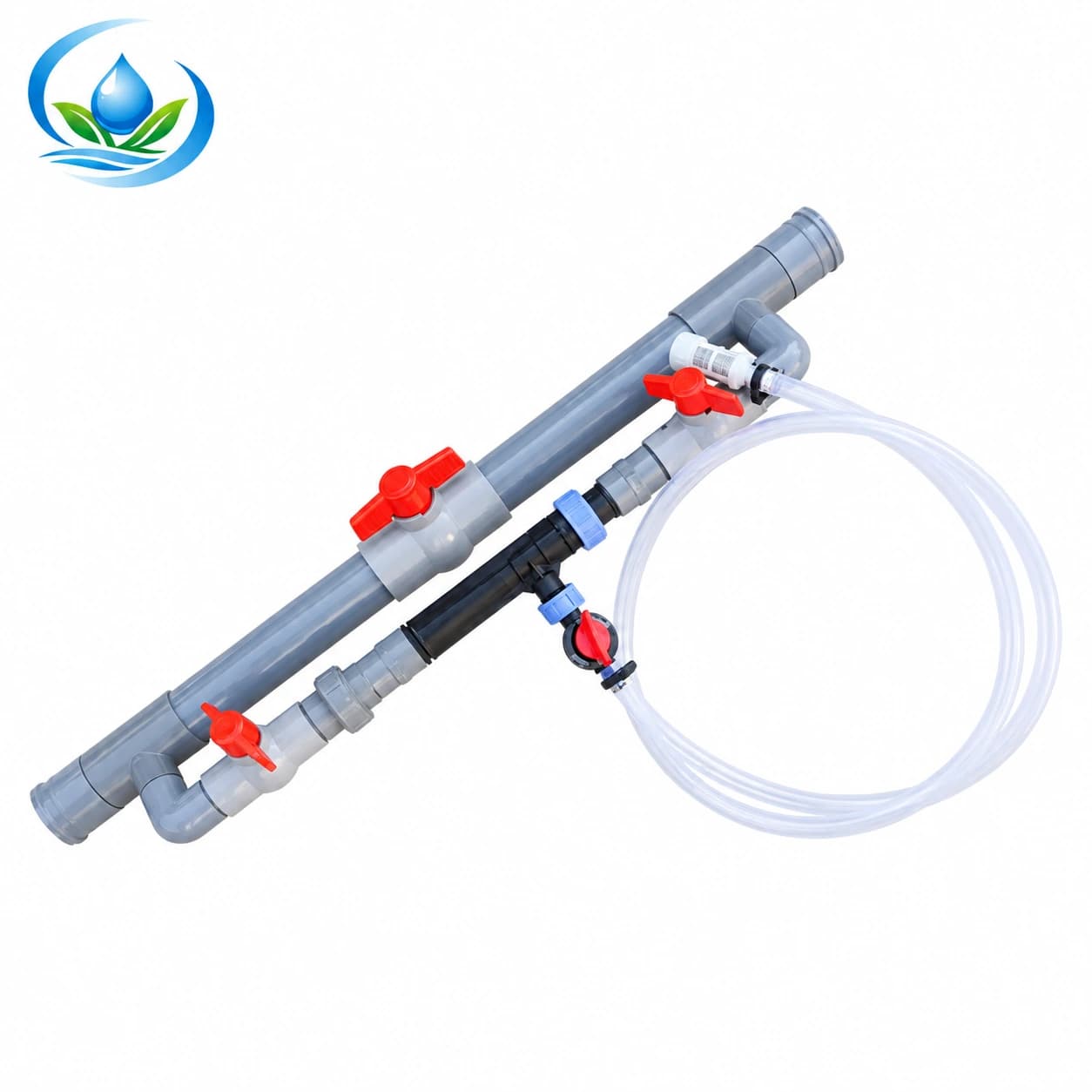
Make a simple drawing from the supply takeoff, through the injector branch, to its return. Mark flow arrows, each control and isolation valve, the suction connection, filters and the positions of existing gauges. Photograph the complete station as well as the injector label. A close picture of the body alone can conceal a reversed branch or a valve that directs water along another route.
Compare present valve positions with the documented working arrangement. A handle direction is useful only when the valve type and function are known; a replacement valve may not share the previous handle convention. Note any missing identification and ask for the installation drawing. Restore settings only through an authorized procedure that also protects the pump and downstream equipment.
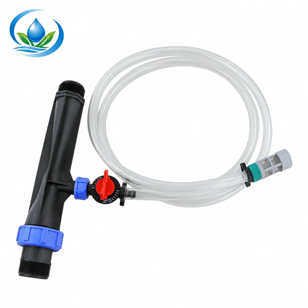
Do not keep closing a mainline valve until the injector begins to draw. An undocumented restriction can overload the operating arrangement or leave the crop network short of pressure. The assembled Venturi set is a route for reviewing a complete bypass configuration, but a set name does not confirm the controls, protective devices or adapters required by your station. Match a proposed assembly to the drawing.
Record pressures at the injector during an approved water run
Use suitable gauges already installed at the required measurement positions, or arrange their safe installation by a competent person before testing. Record the pressure upstream and downstream of the injector during the same stable operating interval. Write the units and gauge locations beside the values. A pump gauge on the other side of a filter or a long pipe does not directly give the injector's inlet pressure.
A Venturi depends on the water passing through it and the pressure relationship across its body. Compare the readings with performance information for the exact model and size. No general percentage drop proves that an unrelated injector will draw. Maximum pressure is also different from the inlet and outlet conditions needed for suction; being below a pressure limit does not establish correct operation.
Record the active irrigation group and any observed variation while taking readings. If a flow measurement is available, identify whether it covers the injector branch or the whole mainline. Those quantities cannot be substituted for one another. The pressure-checking guide helps organize running measurements, while the actual injector documentation determines which operating cases are permitted.
When earlier measurements exist, compare the same locations and units. A different filter condition or downstream demand may explain why a previously useful setup now behaves differently, but the readings alone may not identify the responsible component. Keep hydraulic evidence separate from the purchase decision until the system's operating case has been reviewed.
Inspect the suction route after another safe shutdown
With the station safely stopped, isolated and depressurized again, examine the accessible suction route as the manual allows. Look for a kink, flattened section, split tube, displaced seal, loose connection or obstructed pickup strainer. Note where each observation occurs. Photograph a suspect part before removing it so that its orientation and connection sequence remain available for a replacement enquiry.
A connection may admit air during suction without showing an obvious outward water leak. Conversely, bubbles or poor uptake do not prove that a particular seal has failed. Check the permitted joints systematically and use only the stated tightening or replacement method. Forcing a thread or adding an unapproved sealant can turn an uncertain leak into a damaged fitting.
Confirm that the pickup position and liquid level meet the manufacturer's arrangement throughout the intended observation. Record the container's elevation and tube route; do not raise the container to force delivery. Also check that the correct valve or control on the suction path is in its authorized position. Any dismantling or cleaning of that component belongs to the model's service procedure.
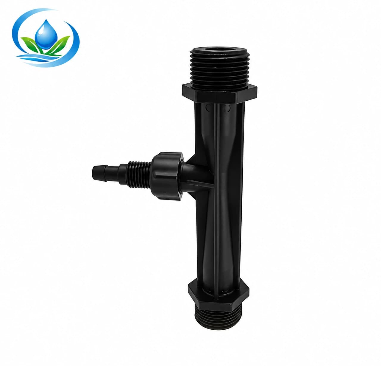
If deposits or damage appear inside the injector, stop at the inspection level permitted to the operator. Do not drill the throat, push wire into a calibrated passage or copy a chemical-cleaning recipe from another model. The Venturi injection tube, reference FRT-VEN-PP, is an injection-section enquiry, not evidence that an unspecified flexible pickup hose fits your unit. Request dimensions and the exact connection arrangement.
Observe a controlled restart with clean water
After an approved correction, reassemble the station and follow its documented restart procedure. Use clean water on both the supply and suction sides for the check, with the source protection and normal hydraulic route intact. Keep the approved container position, pickup immersion and irrigation group consistent. Do not disconnect the outlet into a convenient bucket if doing so changes the required downstream condition.
Choose a permitted observation interval and record its start and finish. Note whether the clean-water level falls continuously, remains unchanged or moves irregularly, along with pressure observations and any visible leakage. A readable vessel and a stable reference make the observation more useful than “it seems better.” End the test before the pickup is exposed, following the normal stopping instructions.
Compare one authorized change at a time where practical, preserving the same operating case. If a hose was replaced and the valve arrangement also changed, label both changes rather than attributing the improvement to the hose alone. Repeat the confirmed case to see whether the behavior recurs. Intermittent uptake should remain an unresolved observation until its cause is understood.
Restored drawing is the point to resume a separate delivery check. Use the clean-water injector ratio procedure when a measured proportion is needed, keeping its volume boundaries consistent. Visible uptake by itself does not verify the required ratio, chemical compatibility or crop dose. A successful run with water also does not establish identical behavior with every stock solution.
Match replacement parts to the identified unit
Decide whether the evidence points toward a changed operating case, a confirmed external service item, physical damage, or a problem still requiring diagnosis. A visibly split hose can justify an exact compatible replacement after confirmation of its material and dimensions. A sound-looking injector that works in one approved zone but not another calls for a hydraulic review before ordering a larger body.
For the Venturi injector options, the catalogue identifies F32V with a 1-inch connection, F50V with a 1½-inch connection and F63V with a 2-inch connection. Their Store order references are IS-44-F32V, IS-44-F50V and IS-44-F63V respectively. Match the marking on the installed unit to its purchase record before selecting a replacement; nominal connection size alone is insufficient.
The catalogue lists maximum suction figures of 300, 780 and 1,200 L/h for those three models respectively. It separately lists maximum water flows of 8, 15 and 20 m³/h, and a maximum pressure of 8 bar. These are individual catalogue limits, not simultaneous operating points. Dividing one maximum by another cannot establish a guaranteed injection percentage, and a larger maximum does not promise recovery in the existing bypass.
Ask for the model-specific performance information and a service-part reference that matches the damaged item. Confirm thread form, sealing method, material, dimensions and included accessories. The injector order-contents guide helps distinguish a replacement body, a suction-side part and an assembled bypass set once the fault and existing reusable pieces are identified.
Send a support record that can resolve the repair
Collect the exact model and order reference, an overall station photograph, close views of the affected part, the bypass sketch and the last successful operating record. Add the present irrigation group, gauge locations and units, permitted valve positions, observations from the clean-water run and the changes made between trials. Identify unavailable measurements explicitly so support does not mistake an estimate for a reading.
Send that record through IrriNex Store support with a focused request: confirm the intended operating case, identify a compatible service item, or review a proposed replacement assembly. Request its current price, availability, exact contents and delivery terms before ordering. Keep the response with the station record so the next operator can distinguish an approved repair from a temporary setting.
After the repair and required verification, save a new clean-water baseline with the date, equipment identity and operating conditions. Label the normal control state where the installation procedure permits it. This makes a later loss of suction a comparison against known evidence and helps the farm buy the part it needs without repeating an uncertain series of adjustments.
Before you order
Compare this guide with the specifications for your exact product, selected option, water supply and field conditions. Your equipment requirements take priority over a general example.
Compare irrigation products