Drip Line Length Calculator: Size Laterals Before Ordering
Convert crop-row measurements into lateral length, approximate emitter count, zone flow, roll quantity, start fittings and flush ends.
Published by IrriNex Store
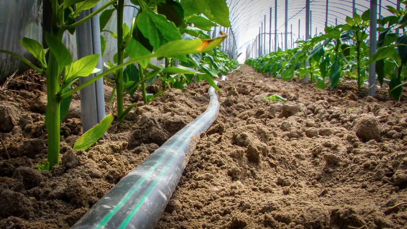
A drip line length calculator converts measured crop rows into lateral metres, approximate emitter count, planned zone flow, roll quantity and matching start and flush fittings. It must keep two numbers separate: total material across the field and the maximum permissible length of any single lateral. Use the worksheet below before choosing an inline dripline or drip tape variant, then confirm the selected product's spacing, discharge, pressure range, roll length and run-length table.
Collect the six inputs that control the order
For each irrigation zone, record the number of planted rows, measured length of every row, number of drip lines per row or bed, selected emitter spacing, selected emitter discharge and the roll length offered for the exact variant. Add elevation direction, inlet pressure and pipe diameter as design checks. Do not replace field measurements with a field-area estimate.
A useful sheet has one row for every group of crop rows that share the same length and product. Separate different beds, headlands, terraces and greenhouse bays. If one row bends, measure the actual route along the ground. Mark unplanted gaps where the line will continue without serving crop, because that material still counts even if its emitters are not wanted.
Distinguish a lateral from a header and mainline
The lateral is the dripline or tape running beside the crop and releasing water. A header or submain feeds several laterals, while the mainline moves water to field blocks. This calculator covers emitting laterals. It does not automatically size the header, mainline, pump or filter.
Draw the water route before counting. Label the connection between the header and every lateral, the far-end closure or flush valve and any place where two pieces will be joined. The farm zone guide helps decide which rows operate together. A correct material total attached to an overloaded zone is still a poor order.
Calculate planted lateral length
For equal rows, use: planted lateral length = number of rows × lines per row × row length. Twenty-four 85m rows with one line each require 2,040m of emitting lateral before allowances. Twelve raised beds 42m long with two lines per bed require 1,008m.
For unequal rows, sum them individually. A practical table might group ten rows at 60m, eight at 74m and six at 81m: 600 + 592 + 486 = 1,678m. If two lines serve each row, multiply each group by two before adding. Keep the arithmetic visible so purchasing can trace the total back to the field.
Add only measured non-crop length
Some layouts need a short service tail, route around an obstruction or extra line for connection and flushing. Measure these lengths or state the allowance explicitly. Do not add an unexplained percentage and call it design. A two-metre service addition on 24 laterals adds 48m, regardless of the field's total area.
Keep header-to-first-plant distance separate when emitters in that section would waste water. The correct solution may be a non-emitting feeder, a closed section approved by the product system or a different header position. Do not assume drip tape can be folded, plugged or buried to cancel unwanted outlets.
Keep total dripline metres separate from the longest lateral
A field can need 4,000m of material while every lateral is only 80m long. Conversely, a small field may contain one 260m row that exceeds the chosen product's hydraulic limit. Total order length answers how much material to buy; maximum lateral length asks whether pressure and discharge remain acceptable along one continuous run. A dripline length calculation needs both values: material metres for purchasing and a single-run length for checking the selected product.
A universal maximum cannot be calculated from diameter alone. Emitter spacing and flow, inlet pressure, wall and internal path, elevation, water temperature and acceptable variation all matter. Use the current run-length or hydraulic table for the exact variant. If it is unavailable, request it before relying on a long row.
Estimate emitter count from spacing
For initial flow planning, approximate emitters per lateral = active emitting length ÷ emitter spacing, using one unit. An 80m active section with 0.20m spacing has about 400 emitting positions. Whether the physical product places an emitter at the first cut depends on its manufactured offset and where the roll is cut, so use this calculation for planning rather than package verification.
Multiply by the number of laterals for the zone total. With 24 identical rows, about 9,600 emitters operate. For irregular lengths, calculate each group. Do not round each small segment down if that would understate zone flow; use a conservative whole-emitter count and verify the selected roll layout.
Calculate planned flow for one lateral
Use: lateral flow = approximate emitter count × selected emitter flow. If 400 emitters each list 1.0 L/h, the planned lateral demand is about 400 L/h. If the product provides flow per 100m, use that current variant value instead of rebuilding it from a different spacing.
This number is the sum of nominal outlet flows under documented conditions. It is not proof that the far end receives the same discharge. Compare it with product hydraulic data and the pressure remaining along the route. Keep litres per hour separate from litres per minute and convert before adding to a pump or filter schedule.
Calculate the flow of the complete zone
Add the lateral flows that operate at the same time. Twenty-four laterals at approximately 400 L/h create a planned zone flow near 9,600 L/h, or 9.6m³/h. Add only simultaneous lines. If the valve opens half the rows at a time, make two operating cases rather than one inflated total.
Compare the result with source flow at working pressure, header capacity, filter range and control-valve rating. The drip irrigation flow-rate guide gives a fuller worksheet. Do not select a filter only from connection size; it must also serve the actual zone flow and water quality.
Check each lateral against the selected product
Create one row for every distinct lateral length. Enter diameter, wall, emitter spacing, emitter discharge, inlet pressure and elevation change. Then compare the longest or most difficult case with the exact product table. The worst case may be an uphill row rather than the physically longest row.
If a lateral exceeds the permitted condition, reduce its length, feed it from a more central header, divide it into independently supplied sections, change the selected variant or redesign pressure and zones. Do not solve an unsupported run by ordering a longer roll. Roll length is packaging, not hydraulic permission.
Calculate roll count from usable dripline length
Use: order length = calculated installed length × (1 + stated allowance). Then rolls = round up(order length ÷ usable length per roll). If installed length is 2,088m and the documented allowance is 3%, the order basis is 2,150.64m. With 500m usable rolls, round 4.30 up to five rolls.
Confirm that the displayed roll length belongs to the selected diameter, wall, spacing and flow. A family page can contain multiple combinations. Ask whether factory leaders, damaged packaging or unusable remnants affect usable length. Keep leftover pieces labelled by exact variant; do not join a visually similar tape with different flow or wall.
Count start fittings, ends and repairs
Normally each independently fed lateral needs one compatible start connection and one serviceable end closure or flush point. Therefore 24 laterals usually create 24 starts and 24 ends, subject to the actual header design. Count valves only where the drawing requires individual control.
Add adapters between the header and start fitting, grommets or takeoffs where specified, and couplers for planned joins. Keep repair couplers as labelled service stock rather than building unnecessary joints into new laterals. A join can be useful when a roll ends, but its bore and retention must match the selected tape or dripline.
Choose among the three current lateral families
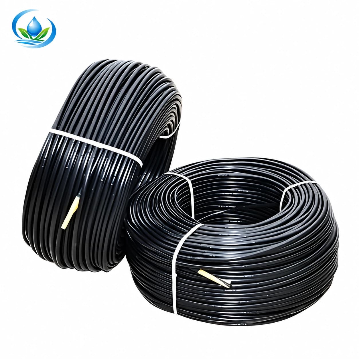
The inline dripline with built-in emitters is a thicker-wall product route for repeated outlets along crop rows. Its title lists 16mm and 20mm options while the current parent size field is narrower, so confirm the selected variant, spacing, flow, wall, roll and pressure data before calculating.
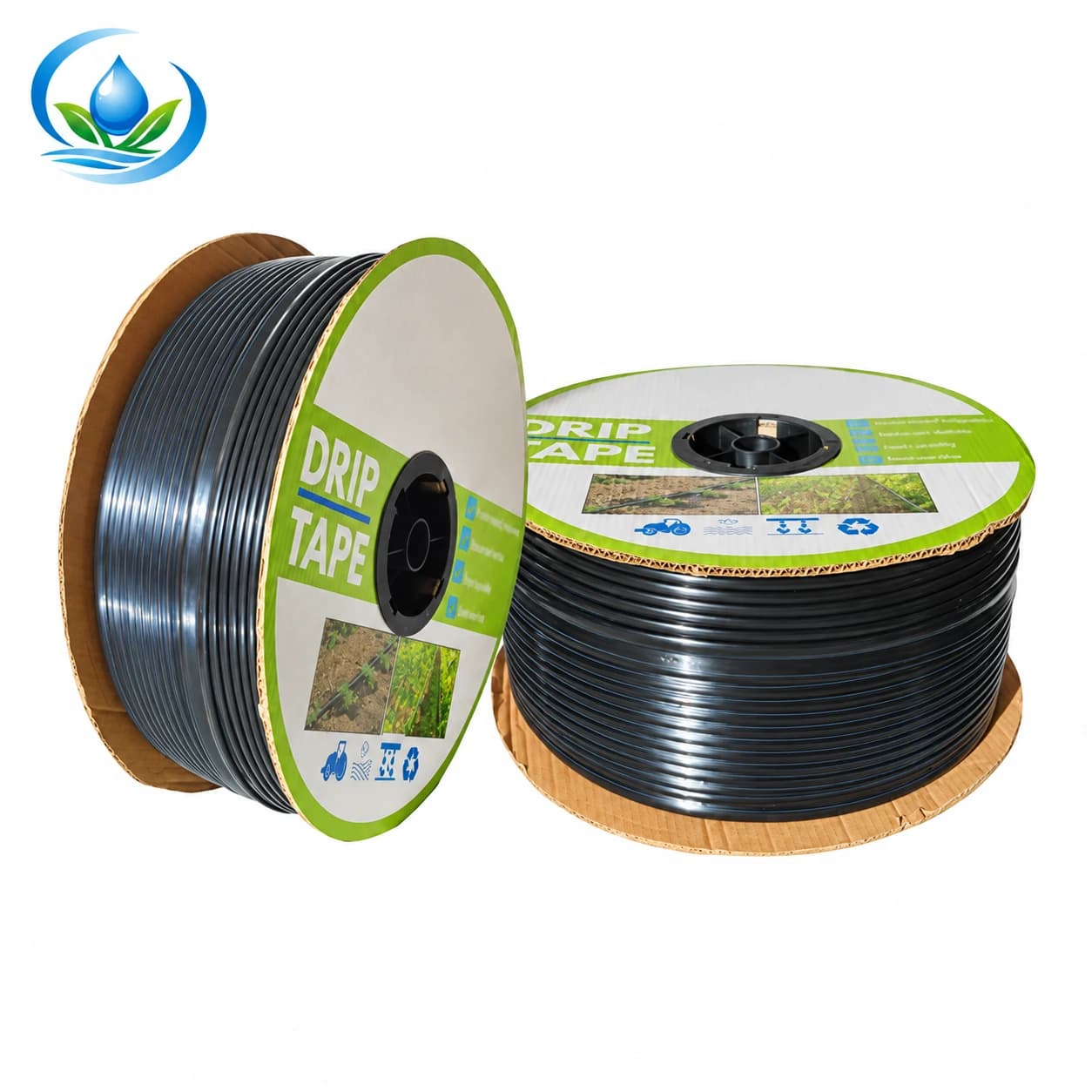
The flat-emitter drip tape is a tape route for vegetable rows, with 16mm/20mm at the family level and a listed family pressure range of 0.04–0.15 MPa. This range does not establish maximum row length; use the selected option’s discharge, spacing, wall and hydraulic data to check the proposed lateral.
Use crop and bed spacing to choose line count
Line count per bed should follow the crop arrangement and observed wetting, not the roll width or a generic kit. Utah State University Extension explains that bed dimensions and crop spacing determine the number of drip-tape lines per bed in its agricultural drip-tape guidance. Soil texture, rooting and cultivation method also affect the useful layout.
Test a representative bed before multiplying one pattern across the farm. If one line does not connect the intended root zone, a second line doubles that bed's material and emitter flow. Update length, zone flow, start fittings and filter calculations together.
Add pressure and elevation checks
Record pressure at the head of the lateral while the full zone operates, then estimate or measure the difficult end. Static source pressure is not the inlet condition. Filters, valves, injectors, header friction and elevation consume or change pressure before water enters the emitting product.
Use the drip-pressure checklist and compare both ends with the exact variant. Thin-wall tape and heavier dripline can have different limits. Never apply the highest family number to all variants or operate a product merely because the fitting holds during a short test.
Include filtration and flush access in the calculation
The smallest emitter path determines a key filtration requirement. Match source water and contaminant type to the selected filter, and size it for the complete operating zone. Review the irrigation filtration guide before completing the head-unit cart.
Every lateral needs a planned method to expel installation debris and accumulated material. Count the closure or flush valve, provide access and include the flushed water route. A calculator that totals pipe but omits service ends produces an installation that cannot be commissioned properly.
Work through a retail example
Assume 18 crop rows at 72m, one line per row, plus 1.5m measured service length per lateral. Planted length is 18 × 72 = 1,296m. Service length is 18 × 1.5 = 27m. Installed lateral length is 1,323m. At a declared 4% order allowance, the purchase basis is 1,375.92m.
If the selected variant is sold in 500m usable rolls, round 1,375.92 ÷ 500 up to three rolls. With 0.30m emitter spacing, approximate active emitters are 1,296 ÷ 0.30 = 4,320. At a selected 1.2 L/h each, planned zone flow is 5,184 L/h. These numbers still require product-specific confirmation that a 72m lateral works at the measured pressure and elevation.
The fitting count begins with 18 starts and 18 service ends, followed by header adapters and a documented spare allowance. A second line per row would double active length, emitters, starts, ends and zone flow; it may also change the correct filter or zone split.
Avoid five calculator errors
- Using field area instead of measured line routes.
- Treating total purchased metres as one acceptable lateral length.
- Using spacing and flow from different product variants.
- Rounding roll count down or hiding the allowance inside row measurements.
- Forgetting starts, flush ends, adapters, filter range and operating pressure.
Keep the input source beside every number: field measurement, selected variant page, hydraulic table or stated purchasing allowance. That record makes recalculation possible when a row, crop or product changes.
Verify the order in the field
- Measure a sample of rows again before cutting.
- Confirm roll label, diameter, wall, spacing and flow against the order.
- Install and flush a representative group.
- Operate the planned zone and measure inlet and far-end pressure.
- Catch water from near, middle and far emitters for the same time.
- Compare delivery and wetting with the crop plan.
- Approve the repeated layout only after the sample performs as intended.
Update the worksheet with actual used length and remnants. If the test requires shorter laterals or a new zone, recalculate rolls and fittings before cutting the remaining material.
Frequently asked calculator questions
Can total roll length tell me the maximum row length?
No. Roll length is a packaging quantity. The allowed lateral run comes from the exact product's hydraulic data and the installation conditions.
Should I round emitter count up or down?
Use a conservative count for flow planning and verify the manufactured offset when cutting. Do not understate simultaneous demand by rounding many groups down.
Does a larger diameter always allow a longer run?
It can reduce friction, but emitter output and spacing, pressure, elevation and product construction remain part of the limit. Use the exact table.
How much extra line should I buy?
State an allowance based on measured service tails, planned joins, site uncertainty and replacement policy. Keep it visible rather than hiding it in every row.
Can different drip-tape variants share one calculation?
Only as separate groups. Calculate their lengths, emitter counts and flows independently, then add simultaneous demand.
Complete the worksheet before checkout
Your final page should list row groups, laterals per row, installed length, selected SKU or variant, spacing, flow, approximate outlets, zone flow, longest lateral, inlet pressure, elevation, roll length, allowance, roll count, starts, ends, couplers and filter. Blank fields identify work still needed.
Compare the current inline dripline and flat-emitter tape. If the selected product page does not show the hydraulic run data required for your longest row, send the worksheet to IrriNex Store support before ordering.
Before you order
Compare this guide with the specifications for your exact product, selected option, water supply and field conditions. Your equipment requirements take priority over a general example.
Compare irrigation products