Irrigation Pump Sizing Calculator: Flow and Total Head in One Farm Case
Create a traceable pump-screening worksheet with simultaneous zone flow, pumping lift, elevation, outlet pressure and route losses.
Published by IrriNex Store
An irrigation pump sizing calculator is useful only when its flow and head entries describe the same operating case. A farm may know the number of emitters but not the water level during pumping, or know the source elevation but omit pipe friction and pressure needed at the last outlet. Put those inputs in a transparent worksheet before comparing pump models. The result is a design point: the flow the selected zone needs at the total head the pump must overcome. A catalogue headline for maximum flow or maximum lift does not by itself prove that a pump can deliver both at that point.
This article builds one model-screening case, then shows what remains for a qualified designer and manufacturer curve. The zone-flow calculation guide develops outlet demand; the solar surface-pump guide compares purchase formats. Here we combine simultaneous flow, pumping lift, elevation, required outlet pressure and losses into a checkable head worksheet. We do not invent an efficiency value, wire size, solar array or guaranteed duty point for a listed pump.
Name the irrigation case before entering numbers
Give each case a plain name such as “north vegetables only,” “small greenhouse only,” or “north plus tunnel, allowed overlap.” List every valve that is open and every other water use sharing the source. Write whether the zone uses drip outlets, sprinklers or a mixture. A calculation for an average day can hide the largest simultaneous demand or the smallest zone that may leave a pump operating outside its intended range. Use the actual permitted control schedule rather than the sum of every outlet in the farm.
Record the water source and its level during pumping, not only the still-water level seen before a shift. Mark pump location and the hydraulically demanding delivery point for the named case. A remote high field outlet may require more head than a nearby branch even when the branch flow is larger. A long pipe may dominate friction while a short rising pipe may dominate lift. The worksheet has one row per operating case so these paths are not accidentally combined into an impossible “worst of everything” configuration.
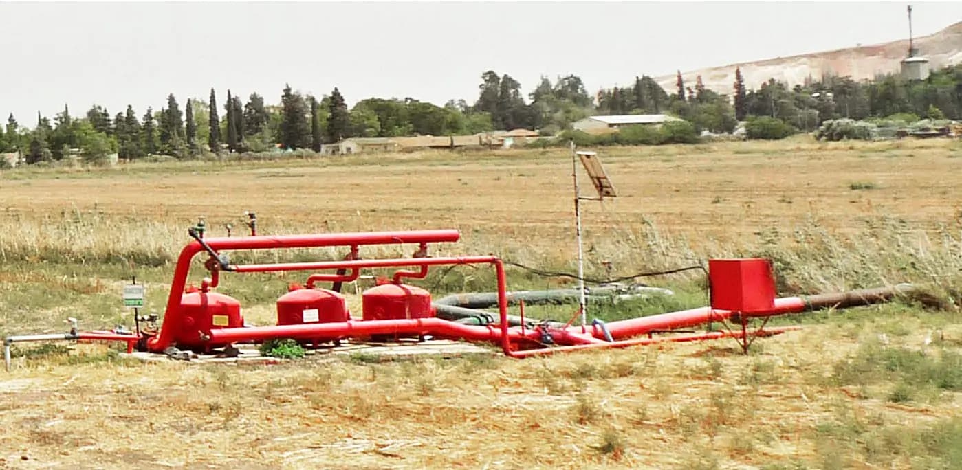
The farm drip-design guide explains why crop rows, zones, pressure and uniformity belong together. For pump screening, attach a route sketch that follows water from the source through pump, filter, mainline, valves, regulators and laterals to the delivery point. The sketch tells you where each pressure loss occurs and prevents a filter or elevation change from disappearing from a calculator cell.
Build the simultaneous flow entry from actual outlets
For a drip case, multiply each distinct outlet group's verified operating flow by the number that run at the same time, then sum the groups. For sprinklers, use the exact head/nozzle combination and its operating pressure data. If a manufacturer lists only a nominal discharge, mark the total as provisional and measure a representative installed zone at its normal pressure. Count intentional non-crop uses that run concurrently, such as a permitted backwash demand, if the system design requires them during irrigation. Do not count a different zone that the controller prevents from opening.
Keep units visible. One model may state litres per hour, another cubic metres per hour and a field meter may read gallons per minute. Convert each figure to one chosen unit before summing, and write the source of each number. A spreadsheet cell that says “4” without units cannot support a pump order. The smallest-zone pump guide is especially relevant when one pump must operate both the main block and a much smaller section; a design that satisfies the largest flow can still perform poorly at the smallest allowed case.
For an illustrative screening example, suppose the named vegetable zone requires 4 m³/h while it operates alone. This is an assumed worksheet value, not a measured recommendation for any farm or a rating assigned to a Store pump. Other cases go on separate rows. Ask which flow measurement or exact emitter schedule would replace this assumption before money is committed.
Add lift, elevation, outlet pressure and path losses once
Total dynamic head expresses the load the pump must meet at the selected flow. For a source below the pump, pumping lift is the vertical difference from water level while pumping to the pump discharge reference. Add the net elevation change from that reference to the delivery point; do not sum every hill climbed and descended along a closed, pressurized route as separate permanent static lifts. Add the pressure head required at the outlet and the friction and device losses along the active path. If the source is already pressurized, its available head belongs in the calculation and the simple suction-lift example does not apply unchanged.
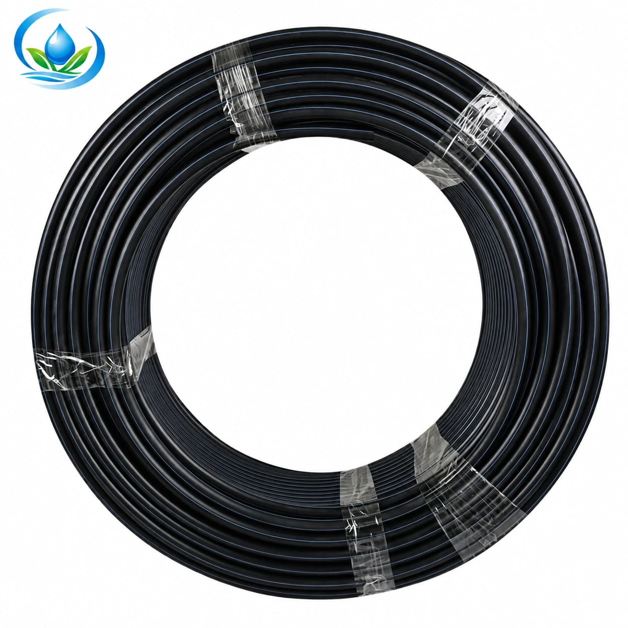
Friction depends on actual pipe inside diameter, route length, material, fittings and flow. The PE irrigation mainline pipe has options with different outside diameters, PE grades, PN classes, SDR and wall thickness. Two 32 mm outside-diameter options can have different inside diameters and therefore different friction at the same flow. Choose the exact proposed pipe before calculating loss; a nominal OD and a generic table are only a starting point. Add the filter, valves, regulator and fittings using data for their intended operating condition.
In a transparent illustrative row, assume 4 m³/h flow, 4 m pumping lift, 3 m net rise after the pump, 10 m pressure head needed at the critical outlet and 6 m combined pipe, fitting and device loss at that flow. The arithmetic gives about 23 m total head at 4 m³/h. The numbers are hypothetical and deliberately rounded. If the filter later proves to lose more head, the design point changes. Do not double-count a pressure figure that already includes part of the route, and do not substitute static gauge pressure for the required operating head at the far outlet.
The Texas A&M AgriLife Extension irrigation pipeline worksheet separates pumping lift, elevation change, operating pressure and friction loss when it calculates total dynamic head. Its pipe tables and worked numbers are examples for their stated materials and units. This article uses that structure, not its example friction value or horsepower result. Have a designer verify the site loss model and the pressure needed by the exact crop equipment.
Plot the point on a complete pump curve
Once the worksheet shows one flow-head pair, obtain a manufacturer curve for each exact pump model at the intended power and speed. Find the flow on the horizontal axis and head on the vertical axis, then see whether the model can operate there and within its allowed range. Repeat for the smallest and largest permitted zones, not only the example row. The required motor, controller and solar supply must be checked for those cases; a model name or watt figure alone does not settle them.
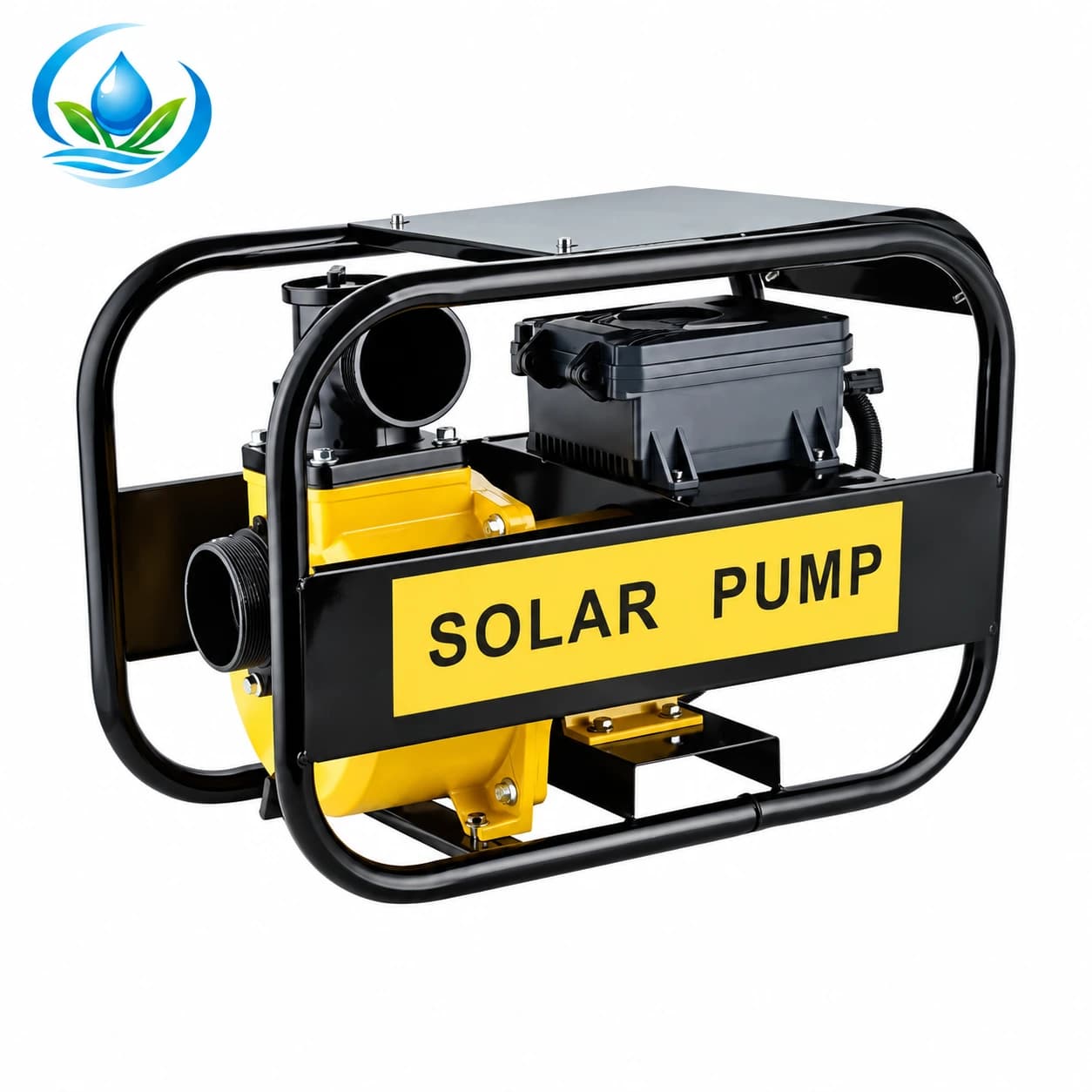
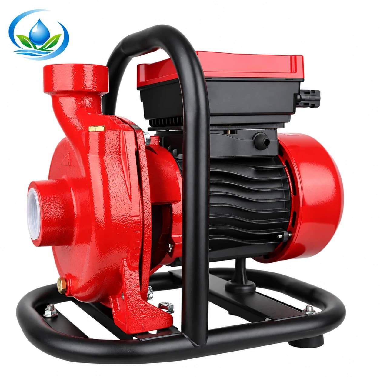
The published ZQD solar brushless self-priming surface-pump family and SCPM solar brushless centrifugal surface-pump family show model labels with flow and head figures. Treat those labels as screening descriptions until the exact manufacturer's performance curve explains the operating combination and test conditions. Do not assume the two largest numbers occur together. Neither family is currently available for direct online ordering; request model-specific curve, price, included controller and current availability.
A pump that can reach the required head at a lower flow may still fail the crop's water demand. One that meets the flow only at a much lower head may leave the last outlets weak. If two models appear to fit one design point, compare efficiency, operating region, source suction conditions, control range, protection and service support with the supplier. Avoid claiming that a self-priming label removes suction limits or that a centrifugal-family name guarantees a certain zone range. These characteristics require the exact model documents and installation design.
Check source, pipe and power constraints around the candidate
Make sure the source can supply the named flow over the planned run time without drawing air, sediment or an unacceptable water level. A surface pump's suction route has limits affected by elevation, line loss and priming arrangement; the exact model manual governs those conditions. If an existing pump repeatedly loses prime, the lost-prime field check helps separate an installation fault from a true model mismatch. A new headline capacity is not a repair for a leaking suction line.
Review the pressure class and interfaces of pipe, filter, regulator, valves and fittings along the route. A pipe marked PN10 or PN16 is not a recommendation to operate at that pressure; include start and stop behavior and any surge that the responsible designer must evaluate. Pipe friction and surge both depend on the installed route and flow. The first pipe size that connects to a pump is not necessarily the economical diameter for a long mainline, and a larger pipe can change the head calculation enough to alter the pump shortlist.
For solar models, determine whether the proposed power supply, controller, storage or water-tank arrangement can support the irrigation window at the design point. Do not convert a label's motor-watt entry into an assumed daily water volume. Weather and seasonal source level matter. If the site uses an existing electrical supply, the required protection and wiring belong to a qualified installer. Keep these questions on the quote rather than adding an invented “safety factor” to a pump number.
Turn the worksheet into a model-specific quote request
Send each supplier the named operating cases, simultaneous flow in one unit, total head breakdown, source level while pumping, pump-to-outlet route, selected PE pipe option, filter and regulator data, desired irrigation window and available power. Ask for a curve marking the proposed model's duty point in each case, operating limits, efficiency information where supplied, suction requirements, included controller, fittings and protection, warranty, current price and delivery. Keep the supplier's assumptions with the reply.
If the supplier cannot place your flow-head pair on a curve, the listing is not enough to approve the model. If the worksheet has an unknown pipe loss or source level, resolve that input before pretending a calculator result is precise. Online ordering is not currently available for either listed pump family or the PE mainline pipe. Request current prices for the exact options and a quote that identifies the included components.
After installation, measure flow and pressure with the intended zone running, including the distant outlet, and compare them to the design case. Record water level, valve states, filter condition and available power. If the installed point differs, inspect the system and its assumptions before changing hardware. A useful irrigation pump sizing calculator produces a traceable flow-head requirement and a shortlist to verify, not a guarantee that a pump will meet crop needs based on two maxima printed beside its name.
Before you order
Compare this guide with the specifications for your exact product, selected option, water supply and field conditions. Your equipment requirements take priority over a general example.
Compare irrigation products