Agricultural Irrigation Flow Meters: Choose the Reading Before the Instrument
Separate live flow, totalized water and pulse-output needs, then check the meter range, measurement boundary and exact installation requirements.
Published by IrriNex Store
Agricultural irrigation flow meters answer different questions depending on what they measure, display and send to another device. A live rate can show whether a valve group is drawing its expected flow now. A cumulative register can show how much water crossed a point over an event. A pulse output can feed a separate logger or controller if both interfaces are actually compatible. Before buying a meter, decide which answer the farm needs, where the measurement boundary belongs and what the lowest and highest normal operating flows are. Pipe diameter alone cannot select a useful instrument.
Write the farm question in the unit the meter must answer
For a blocked lateral or an unexpected pump duty, the useful first reading may be instantaneous flow such as m³/h or L/min while a named crop group runs. For an irrigation-event record, the useful reading is accumulated volume such as m³ or litres between two dated observations. These are different quantities. A screen that shows 12 m³/h is a rate at that moment; a register change of 12 m³ is water measured across the whole interval. Do not multiply a momentary rate by an event duration without evidence that the rate stayed representative.
The Mississippi State University Extension explanation of flow-meter totalizer readings distinguishes instantaneous rate from accumulated volume and stresses the displayed unit and multiplier. If the buyer already has a suitable meter and wants event volume, the farm-block meter-reading guide works through that calculation. This purchase guide begins one step earlier: specify the register, rate display and resolution that a new instrument must provide for the job.
Write one sentence beside each intended user. The irrigator may need a legible local totalizer at the pump. The crop manager may need a stable rate during the smallest drip zone. A record system may need pulses or another documented signal and a known volume per pulse. Those needs can be combined in one suitable model, but the word “digital” does not prove that a meter includes all three. Ask what the exact offered instrument displays locally, what output it provides, whether its output needs external power and how a reader will recover the total if a controller is offline.
Place the measurement boundary on the actual water route
Draw the source, pump, filter, tank if present, manifold, active valves and fields. Circle the pipe where the proposed meter would sit. A meter before two field branches totals both when both run. A meter after one branch split describes only that branch. A meter before a storage tank records water entering the tank, which may differ from water leaving for crops while its level changes. Give the reading a name that matches that boundary: “pump discharge total,” “north block total” or “one-zone rate,” for example.
When diagnosing a new zone, compare what is included in the proposed reading with the crop outlets actually running. The drip outlet-flow guide estimates demand after the exact emitter and active count are known; it does not turn that estimate into a measured source flow. The zone grouping guide helps name the cases. If fertilizer is injected or a filter backwash uses water between the proposed meter and the field, record that route before assigning all totalized water to crop irrigation.
The listed PE mainline pipe illustrates a possible location for a farm supply meter, while the manual maxi valve and inline dripline illustrate downstream control and crop delivery. They are not flow meters, and their product pages do not supply a meter model or compatible measuring insert. Use their actual installed positions to describe the circuit to a meter supplier; do not choose a meter merely by copying the size of a linked Store component.
Check the smallest and largest flow the chosen point will see
List the normal operating cases at the proposed meter position. Include the smallest single drip group, a typical group, the largest permitted combination, and any non-irrigation use that actually crosses the meter. Record both rate and pressure under each case if safely measurable. A unit sized only for the pump's maximum may be insensitive when one small valve opens. A unit chosen for a small group may be outside its documented range when two large groups run. Find the exact meter's minimum measured rate, normal rated flow, permitted maximum, accuracy statement and pressure loss for the conditions that matter.
Manufacturer meter catalogues distinguish minimum, transitional, nominal and maximum flow values and can attach different performance or installation conditions to each. Those are model-specific instrument data, not Store pump or pipe ratings. A nominal “two-inch meter” can have a different low-flow capability from another two-inch technology. Keep the measured range and water characteristics with the model code. If the source carries sediment, air or changing conductivity, ask which meter technology and installation the maker approves for that water; a clear-looking sample or the mainline size does not settle it.
Suppose, purely to frame a request, that the smallest normal group draws 3 m³/h and the largest combination draws 28 m³/h. The selected meter needs a documented useful range spanning both if one instrument will measure both at the same point. These are hypothetical farm observations, not published IrriNex pipe or meter performance. If the chosen meter cannot cover both within the accuracy needed, review the measurement location, separate branch meters or a different instrument. Do not write “3–28 m³/h approved” on a product order until a specific maker's table covers the actual conditions.
A pump's maximum-head and maximum-flow labels are separate endpoints, not the meter's observed operating range. The pump working-point guide helps establish what the source can deliver while the crop load is connected. Likewise, a field leak may make a measured flow higher than the planned emitter demand; the leak-location guide helps trace that discrepancy before the farm blames the meter.
Reserve the installation conditions before ordering pipe work
Ask for the exact meter's drawing and installation manual, then check flow direction, permitted horizontal or vertical orientation, full-pipe requirement, upstream and downstream straight-pipe lengths, space to read and remove the register, and any filtration or access instruction. Different meter designs have different requirements. One manufacturer may require substantial straight lengths around a particular mechanical meter while another model in its range allows a different arrangement. Therefore no generic number of pipe diameters in an article should be copied onto every installation.
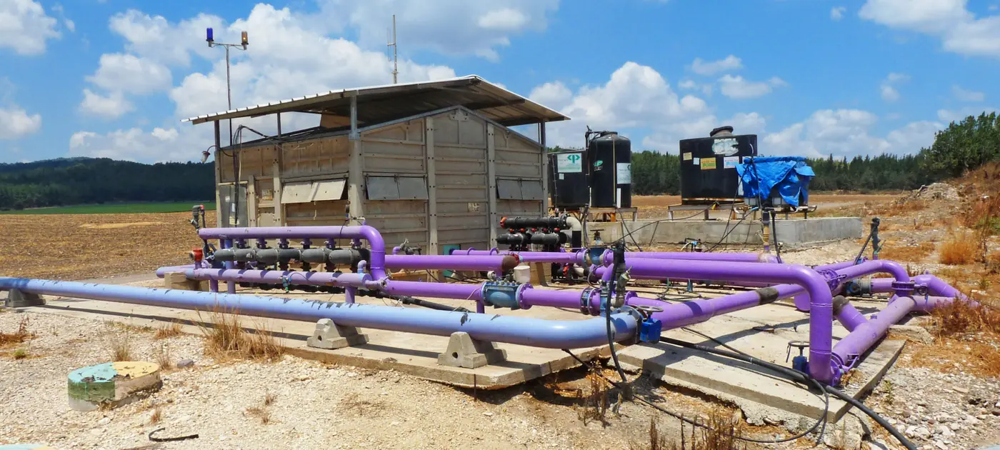
Look at the actual headworks. A valve, bend, reducer or pump outlet immediately beside the proposed location may leave too little stable pipe for the selected device. Moving the meter downstream can change which branch it measures. Moving it upstream can bring storage filling or a bypass into its total. Draw both the physical space and the measurement boundary before cutting a mainline. Verify the exact mating connections, pipe support and pressure rating; nominal size does not identify thread standard, flange drilling or an approved transition.
Keep the instrument accessible after the crop and other equipment are installed. The display should be readable in the normal safe operating area, its seals or register serviceable under the manufacturer's isolated procedure, and its cable protected if a pulse or data output is used. The headworks service-space guide addresses adjacent filters and injectors; this meter needs its own maker-specific removal and reading space. Never cut a live mainline, open a pressurized meter body or improvise an electrical connection from a photograph.
Define the register, multiplier and signal before connecting data
For manual logging, ask whether the local register stores cumulative volume, what each digit represents, whether a multiplier is printed beside it, and what happens at a rollover or power loss. A display may show several screens; the rate screen and total screen need distinct labels in the field record. An operator should be able to photograph the meter identity, unit and full reading at the start and end of an event. If the least readable increment is too coarse for a short zone event, choose another supported register or observation interval instead of reporting false precision.
For remote logging, identify the exact output form, pulse value or communication protocol, required supply voltage, cable limits and compatible input on the intended logger or controller. A pulse-capable meter does not automatically include a logger, network connection, valve actuator or water-use alarm. A controller with a generic “sensor” terminal does not prove it accepts that meter's pulse form. Get both manuals and a written interface pairing before buying the cable and electronics.
For illustration, if a confirmed output represents 100 L per pulse, 250 counted pulses would represent 25,000 L, or 25 m³, across the defined boundary. Those numbers are not settings of any linked Store item. Missing pulses, a misconfigured value or a counter reset would invalidate the simple multiplication. Keep a local register reading, if offered, as a cross-check and write the volume-per-pulse value into the commissioning record. Never copy a pulse value from a visually similar meter body or another diameter variant.
Accept the installed meter against a named crop case
Before installation, record the selected make and model, measuring technology, size, connection, water suitability, flow range, pressure loss, register unit and any signal option. Have the qualified installer follow the maker's flushing, orientation, pipe support, isolation and wiring instructions. Record a baseline with the intended zone at ordinary running conditions. Observe the meter reading, other safe pressure and flow points, valve state and any unusual air or leakage. If the new device adds a meaningful pressure loss to a marginal drip group, the pipe and irrigation design need review rather than hiding the loss in the crop result.
Check the meaning of a total before using it in a decision. As a hypothetical example, a register reading 12,450 m³ before a defined event and 12,480 m³ after it shows 30 m³ crossing the meter. If a second block or tank fill was active, it remains a combined 30 m³ measurement. The instrument cannot tell the operator which crop received which share unless the boundary or operating record separates them. The existing-meter guide explains the subtraction in more detail; this commissioning check asks whether the instrument and its placement provide the answer originally requested.
Ask for the meter's supported field verification or calibration process when an official water account or precise performance comparison depends on it. One plausible reading does not certify the meter throughout its range. Keep the installation drawing, model documents, pulse mapping, first readings and service record with the farm's irrigation plan. The final order should name the exact meter specification and the pipe work required to place it correctly. Store pipe, valve and dripline pages can help identify the water circuit, while the meter itself must be sourced and documented as a suitable instrument.
Before you order
Compare this guide with the specifications for your exact product, selected option, water supply and field conditions. Your equipment requirements take priority over a general example.
Compare irrigation products