Irrigation Design: Leave Service Space Around Filters and Fertilizer Injectors
Check the selected head-unit models against their real service path: filter withdrawal, reachable isolation, injector suction access, support and water collection.
Published by IrriNex Store
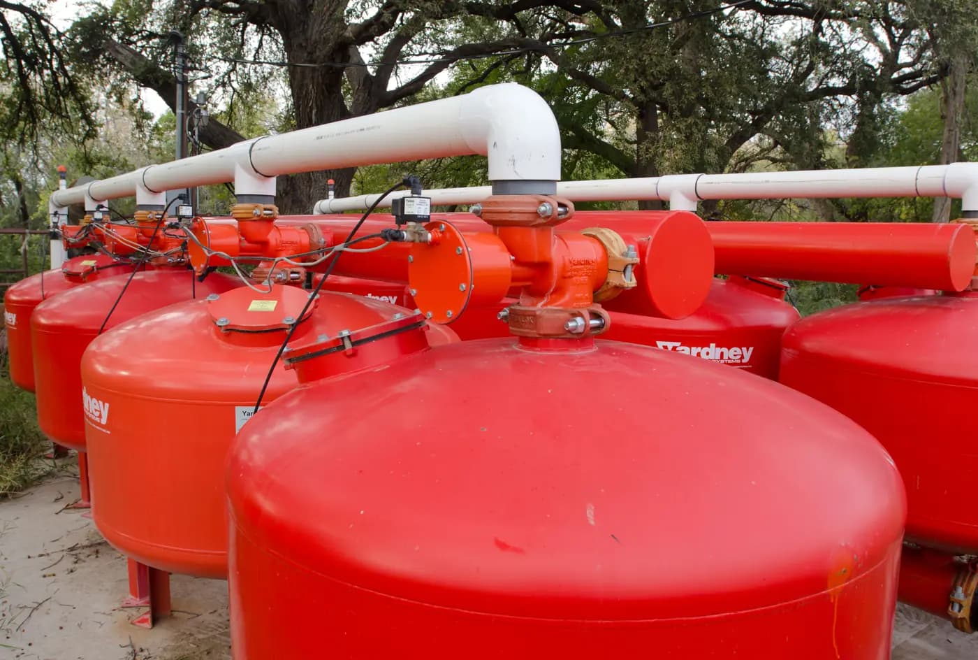
Irrigation design at a farm head unit must leave space for the work that will be done after the filter and fertilizer injector are installed. A disc filter can fit between two pipes yet be impossible to open or withdraw without striking a wall. A dosing pump can be visible from the path while its suction connection is trapped behind a frame. Before buying or mounting the selected equipment, draw its actual service path, the operator's safe access and the route for water released during approved maintenance. Irrigation filter maintenance clearance includes the path for withdrawing the selected filter body and a place for water released under the approved service procedure.
Start with the hydraulic and water-quality choices already made for the farm. This planning step checks whether those exact chosen models can be isolated, observed and maintained in the proposed physical location. Bring the model-specific installation and service instructions, the pipe-connection schedule and a sketch of the head assembly to the installation site. Record an unresolved dimension as an open decision rather than filling it with a clearance number from another brand.
Reserve filter service clearance at the headworks
On a plan and a side view, mark the incoming water route, filtration units, chosen injector, pressure and flow measurement points, existing isolation controls, supports, floor or ground level, nearby wall, fence and traffic path. Identify the normal flow direction using each selected unit's own marking and instructions. Show every branch that could remain pressurized from another source or automatic start. This is a physical survey of a chosen arrangement; the farm drip design guide covers the earlier calculation of source flow, pressure, crop rows and zones.
Photograph the bare site from the operator's approach and from both ends of the intended pipe route. Measure the free width and height, the location of fixed obstructions and the space occupied by the current pipe and supports. Include a door's swing, a cabinet opening, a walkway used by equipment and access to drain or collection points. A plan that looks roomy from above can fail in elevation when a filter element must travel downward, sideways or upward according to its exact model.
Do not treat a catalogue picture as the assembled footprint. A photographed filter may be sitting on a display stand or shown without the adapters, valve handles, pressure taps and pipe braces that the installation needs. A dimensional table can identify a housing's outside size yet still omit the path needed to disengage its element. Request the exact model drawing or service instructions when that path is not documented.
Plan disc filter removal and injector access paths
For every filter body, name the part that must move for routine inspection: a cover, bowl, disc cartridge, seal holder or another component specified by its manufacturer. On the sketch, outline the body in its proposed orientation and draw the full path that component takes out of the installed unit. Include the space needed to grasp it, place it on a clean surface and return it without contacting a wall or pulling against nearby pipe. Do this with the actual option, not just a Y-body or T-body family name.
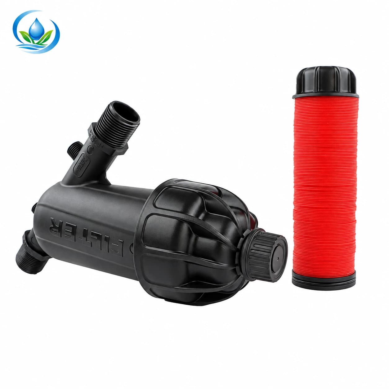
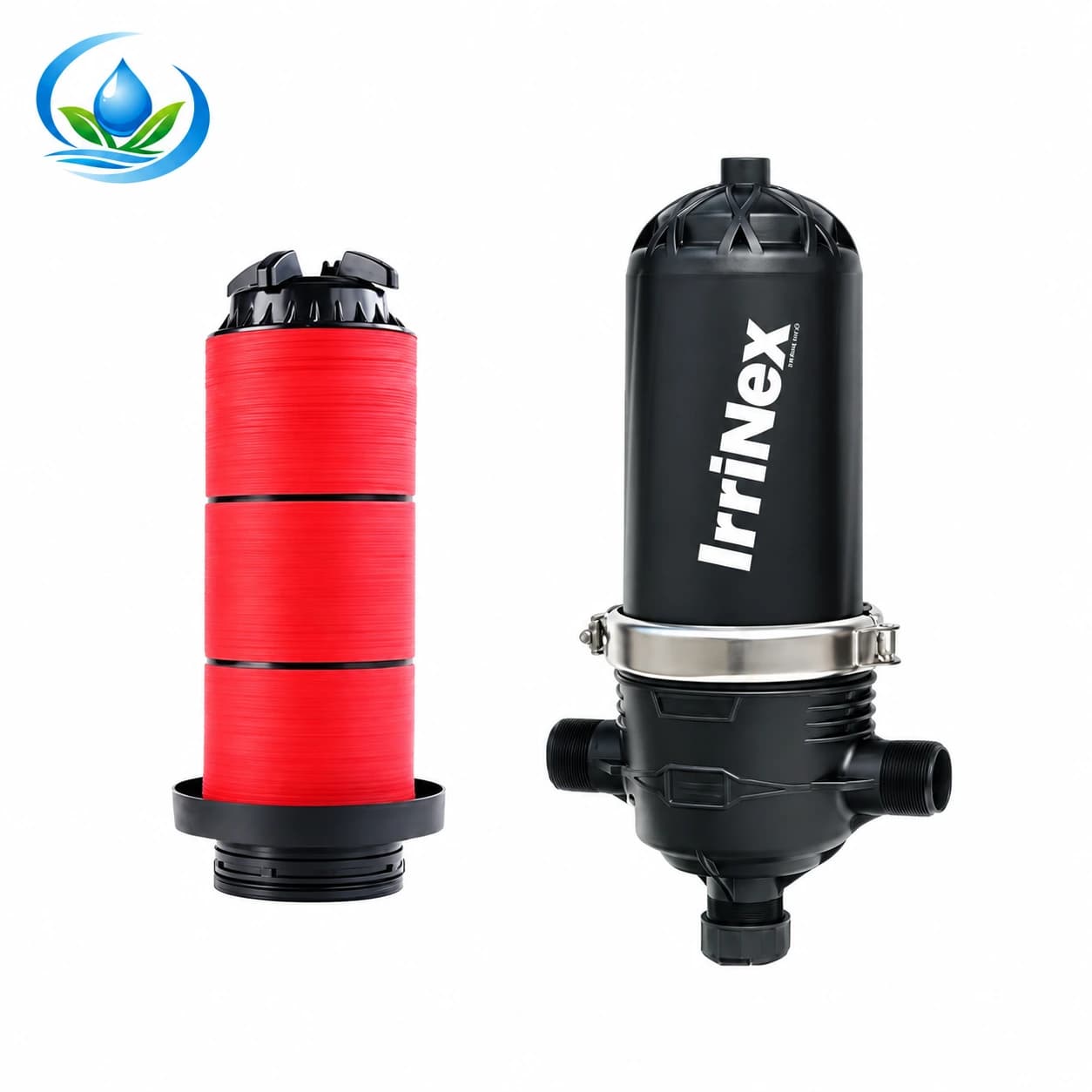
The Y-body disc-filter options and T-body disc-filter options provide two shapes to compare against a real pipe route. Their listed connection and filtration figures help identify an option for further review. Maximum flow and maximum pressure are separate limits; confirm the model's working point and pressure loss for the actual zone. Its body dimension alone does not prescribe safe clearance around a mounted unit. Confirm the chosen model's opening direction, supported mounting, connection standard and complete withdrawal path from its own instructions.
Put a temporary outline at the intended location before pipe is cut. Cardboard or tape can show the housing size and likely interference with a wall or frame, but a guessed cardboard shape does not replace a manufacturer drawing. Where no reliable removal path is available, hold the layout decision until the exact element and housing information arrives. Rotating a component on the drawing only helps if that orientation is permitted for the selected unit and the pipe connections remain suitable.
Check each filter separately when several bodies share one head. The first cartridge may clear a wall, while the second hits a neighboring bowl, gauge or support. Allow a clean landing place for removed parts and a way to keep each filter's seals with its own body. The disc-stack return-to-service guide explains why parts from similar housings should not be mixed after cleaning. This layout decision is made before those parts are ever removed.
Make isolation and observation reachable
Locate the controls identified by the installed equipment's approved isolation and depressurization procedure. Can the operator reach and identify them without leaning over a pressurized connection or walking through standing service water? Can a later technician see the unit label, flow arrow and measurement points? Record any automatic pump or alternate feed that the approved procedure must control. A stopped pump or low reading at one gauge does not establish that the filter or injector is safe to open.
Do not use a service sketch to invent a bypass that would deliver unfiltered water to crop outlets or to avoid required source protection. If an existing bypass or parallel route is present, label its normal and maintenance states according to the system designer's instructions and include its handles in the reach check. The purpose is to reveal a trapped valve or ambiguous route before installation, not to authorize live valve experiments or disassembly while a housing is pressurized.
Where the chosen model and site permit pressure readings, leave gauges or ports readable in the normal operating position. The useful record identifies both sides of the filter, the active zone and flow case, not one isolated pressure number. The screen-filter service decision guide uses comparable inlet and outlet readings to separate loading from other symptoms. A mounting location that hides one tap makes that later comparison harder. Obtain the exact manufacturer's clean and service criteria rather than borrowing a trigger from another filter.
Protect the injector's service side as carefully as its water ports
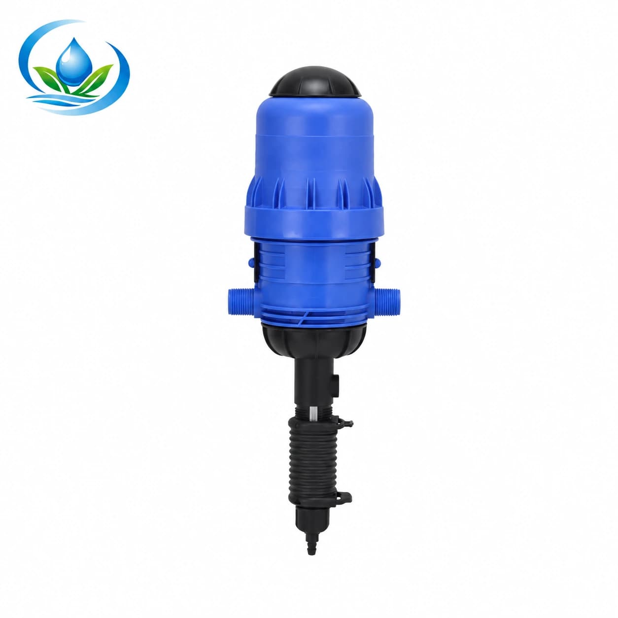
Sketch the fertilizer injector with its actual water inlet and outlet, the suction side and the parts the manufacturer says the operator may inspect or replace. The water-driven dosing pump listing identifies an option to examine. Before fixing the surrounding pipe frame, obtain the drawing, ratio and flow ratings, and service sequence for the exact selected unit. Include the space for every component that its instructions require the operator to reach or remove.
Allow the person who runs the station to read the setting and model label, observe the suction connection and reach any approved service point without disturbing a filter housing. Route the suction line so it remains identifiable and supported, with the stock container in a permitted, stable location. A line hidden behind the filter or stretched tight around a corner can turn a small inspection into a head-unit shutdown. Follow the actual equipment and input instructions for container location, tubing support and any required containment.
Make a separate space entry for water-only verification. The injector ratio-test guide explains the measured clean-water trial after an installation exists. Here the question is whether its suction vessel, observations and controls can be reached without changing the operating route. Do not relocate a tank or remove protective equipment merely to make a test easier. If a safe test arrangement cannot fit, revise the head location before installing the injector.
Once the injector route is selected, the injector contents guide helps identify which body, suction pieces and bypass parts the order supplies. This site-space check uses the actual selected components and their service drawings. Follow the model and local requirements for flow direction, source protection and injection arrangement; a generic schematic cannot certify the parts or protective devices needed at this location.
Decide where service water and removed material will go
Servicing a filter can release retained water and captured debris. Mark where that water can be collected or discharged under the site plan, away from electrical equipment, stock solution, clean filter parts and a walking route. An outdoor location still needs a deliberate route; a low point beside a valve may turn into mud and block access after the first wash. Keep the service area stable enough for a person to carry a wet element without stepping across loose pipe or hoses.
Identify a clean surface for an element, core and seals while the unit is isolated and opened according to its manual. Keep dirty wash water separate from the clean side of the housing. If the maker requires an approved wash or drain arrangement, allow for its connection and collection without running discharge across the operator's feet. Do not infer a cleaning chemical, a universal wash interval or a drain flow rate from the available space. Those are different decisions based on the exact equipment and water source.
Consider the next person who will do the work after crops, mulch, weeds or stored supplies have changed the surroundings. Leave the identified access path available during the season, and mark anything that must remain clear on the site drawing. If a vehicle or cultivation route crosses that path, protect the head unit as required by the project while keeping the service face reachable. A filter sheltered from traffic but buried behind permanent bracing is still a poor layout.
Support pipework without closing the service path
The weight and movement of the connected pipework should not be carried by a plastic filter housing or dosing pump unless the exact equipment instructions allow it. Mark proposed pipe supports and the loads they carry, then check that brackets do not block a cover, cartridge or valve handle. Record pipe diameter and connection standard on both sides of every chosen body. A nominal port size does not prove the mating thread, gasket or adapter is correct.
Do not add a union automatically because another installation has one. The need for a removable joint, its position and approved sealing method depend on the model and the designed pipe arrangement. Ask whether the selected filter's element can be withdrawn without moving pipe; if the full body must be taken out, document its approved isolation and disconnection sequence. Size the physical access around that actual service method.
Check mechanical reach with the actual people and tools expected to service the station. A handle that can be touched by fingertips may still be impossible to operate safely. A cartridge path that clears an empty frame can be blocked after a gauge or tank is added. Repeat the physical survey against the complete parts schedule before ordering fittings or drilling mounts. If the operator cannot demonstrate a safe path on the drawing, keep that interference open for redesign.
Turn the drawing into an exact order and installation check
Use a short worksheet for each component. Record the chosen model, product link, connection ends, actual housing drawing, required orientation, named removable part, movement direction, distance from fixed obstructions, isolation and pressure-release reference, support locations, measurement visibility and discharge route. Put “manufacturer confirmation needed” beside any unknown dimension or operation. Use the exact manufacturer's clearance and removal path before a fixed wall, bracket or pipe closes the service face.
Compare the exact Y-body or T-body filter option on its product page after the water-quality and zone-flow selection is settled. For the dosing pump, confirm the selected model and actual package contents. Check the current item, unit, price, availability and delivery on each product page. If the removal drawing or connection standard is missing, request that exact documentation before choosing a mounting location. The filtration selection guide remains the reference when the filter type or grade itself is still undecided.
Before installation, place the actual body or a manufacturer-accurate dimensional template in the marked location and trace every approved service movement. Check all valve handles, gauges, suction access and collection points in the same walk-through. After the installation is commissioned by the approved procedure, record the normal zone condition and confirm that visible inspections can be performed from the designated safe path. Opening a pressure housing is not part of a live acceptance walk-through.
| Physical check | Evidence to keep | Redesign if |
|---|---|---|
| Filter withdrawal | Exact model drawing and unobstructed part path | Cover or element reaches a fixed object |
| Controls | Approved isolation reference and reachable labeled handles | An alternate feed or handle cannot be identified |
| Measurement | Visible ports, named zone and readable operating location | One side is hidden or the reader must cross hazards |
| Injector | Delivered-model drawing, suction route and water-only test access | Service requires moving protective equipment |
| Water and supports | Collection route, clean parts surface and support positions | Discharge or a bracket blocks safe work |
The final plan should let the next operator identify what can be isolated, what can be read during operation, what moves only after the approved pressure-release procedure and where that part will travel. Order and mount the exact components only when those paths fit the real site. That record makes filter cleaning and injector checks practical throughout the crop season without guessing about a clearance borrowed from another machine.
Before you order
Compare this guide with the specifications for your exact product, selected option, water supply and field conditions. Your equipment requirements take priority over a general example.
Compare irrigation products