How to Drain Irrigation System Lines: Map Low Points Before Buying End Fittings
Map low points, separated branches and component chambers before buying a drain or end fitting. A zero gauge reading does not show that each section is empty.
Published by IrriNex Store
If you are asking how to drain irrigation system lines before an inactive period, start with the shape of the installed water path. Closing the supply and seeing a zero pressure reading at one gauge do not prove that every lower bend, valve chamber or isolated branch has emptied. A practical field drawing identifies where water can leave by gravity, where air can enter through an approved route, and which pockets may remain between those points. Only then can you decide whether an end fitting, accessible drain or model-specific service is actually needed. Mark each low pocket separately from the point where pressure was relieved; a closed valve may place those observations in different sections. Irrigation line low-point drainage needs a map of the sections actually isolated, not just one pressure-gauge reading.
Imagine a vegetable block with a sloping header, several tape rows and one low crossing under a track. Water stops flowing at the far row ends when the supply is isolated, yet the crossing lies below both the headworks and those ends. A replacement end cap at the far row may protect an opening, but it cannot prove the low crossing is empty. The useful buying question is which segment retains water, how its installed design allows it to drain and whether any proposed fitting provides access at the relevant point.
Where can water remain after an irrigation line is drained?
Walk the visible system with a plan or field sketch. Mark the source, pump, filter, pressure regulator, backflow device if present, manifold, headers, laterals and ends. Add changes in height, including dips below a road, low corners, raised loops and equipment installed below the adjacent pipe. Label every branch and valve that may separate one section from another. A line that looks continuous on paper may become several independent water pockets when a control valve or check device closes.
Give each section a name that a crew can find without guessing: “north header after filter,” “track crossing to east valve” or “row group B low bend.” Mark which sections remain in service for a cool-season crop and which are being prepared for inactivity. The winter parts and storage guide covers identification, removal and the return inventory. This drawing has a narrower purpose: determine where retained water can physically go and where an inaccessible low point still needs a design decision.
Use observed elevations rather than the direction in which the pipe was installed. A tube laid toward the end of a row can dip into a wheel rut and rise before its cap. A valve box can sit below the pipe on either side. Photograph the high and low transitions and note whether the ground hides the profile. If the buried route is uncertain, mark it unknown and obtain the layout or appropriate site review; do not cut a line to discover its depth or assume an unseen run slopes as the surface does.
For each named section, ask three separate questions: Where is its actual lowest water-holding point? What approved opening lets water leave that section? What approved air path can replace the departing water? A low outlet alone may not drain a section separated from air by a closed device; an air inlet alone does not create a lower outlet. University of Georgia Extension's winterization checklist notes both low-point access and retained water in components. Apply the exact equipment instructions to your installation rather than copying a generic valve position from another layout.
Does zero pressure mean every low pocket is empty?
Identify how the installed system is isolated and protected against automatic restart before anyone handles a fitting. Then use its designated pressure-release and verification method for the specific section. A stopped pump, quiet emitter or gauge at zero at the headworks is not proof that an isolated lower chamber is empty or safe to open. The planned line-work isolation guide deals with the work boundary and pressure state. This article starts after those requirements are settled and asks what water remains.
Keep the water sources on the drawing even after the pump stops. A raised tank, shared header, connected branch or water held uphill can continue to feed a lower point by gravity. A closed check device can prevent reverse flow or separate a component that needs its own approved drainage access. Do not take a visible trickle as proof a control has failed; trace which section can supply it. Equally, the absence of a trickle at one outlet says little about a sag behind a rise or a vessel with a closed port.
Mark retained-water candidates before removing any closure: filter bowls, pump housings, regulators, meters, backflow assemblies, valve bodies and injector connections can have chambers below their visible ports. Their makers may provide dedicated drains, removable parts or service instructions. A row-end opening cannot empty every one of those chambers. If an exact device's instructions require qualified service, place it on a service list rather than trying to open its housing as an improvised drain. Keep source protection and electrical equipment under their proper procedures.
Separate gravity drainage from a flowing maintenance flush. The lateral flushing guide runs water through an approved row-end outlet to remove mobile debris during service. Here, the supply is being taken out of use and the question is whether static water can leave low sections through approved access. A line may have been flushed successfully yet still retain water in a lower bend after shutdown. A clear-looking flush and a quiet endpoint are therefore not drainage evidence for the full route.
Build a low-point access record
At each suspected low point, write the section name, visible pipe or component model, elevation relationship to its likely outlet, current access, and the maker's drainage instruction if available. Note whether an authorized discharge location is present and where any liquid would go. This is especially useful at a track crossing, buried manifold, downhill header termination or component mounted below its service connection. Do not assign a universal drain time or tilt angle; material can remain behind internal partitions or a rise even after dripping stops.
Classify the result as “documented drain path,” “documented separate service” or “unresolved.” A documented path identifies both the particular outlet and the permitted air route or device condition required for that section. Separate service identifies an exact component procedure and the person responsible for it. Unresolved means that the field sketch or product instructions do not establish how the water leaves. That status is not a failure of recordkeeping; it tells you which design or service question must be answered before buying a cap or calling the zone prepared.
If the installed design allows a controlled check, record what can actually be observed at the approved outlet and which section was connected at the time. A short discharge proves only that some water left. It does not quantify unseen retained volume elsewhere. An inaccessible low pocket may call for a new service point, a layout revision or model-specific removal by the responsible installer. Arrange that decision from the real drawing, especially where a permanent modification might affect pressure, protection devices or future crop irrigation.
Plan for water identity and destination as well as access. A system recently used for fertilizer or treatment may retain material subject to its label and site disposal process. Do not route an unknown residue into a ditch or source because the low point happens to be nearby. Keep the receiving area stable and away from electrical gear, traffic and crop handling. The chosen outlet must be accessible without loading an unsupported pipe or requiring a worker to reach into a live connection.
Decide what the Store fittings can and cannot do
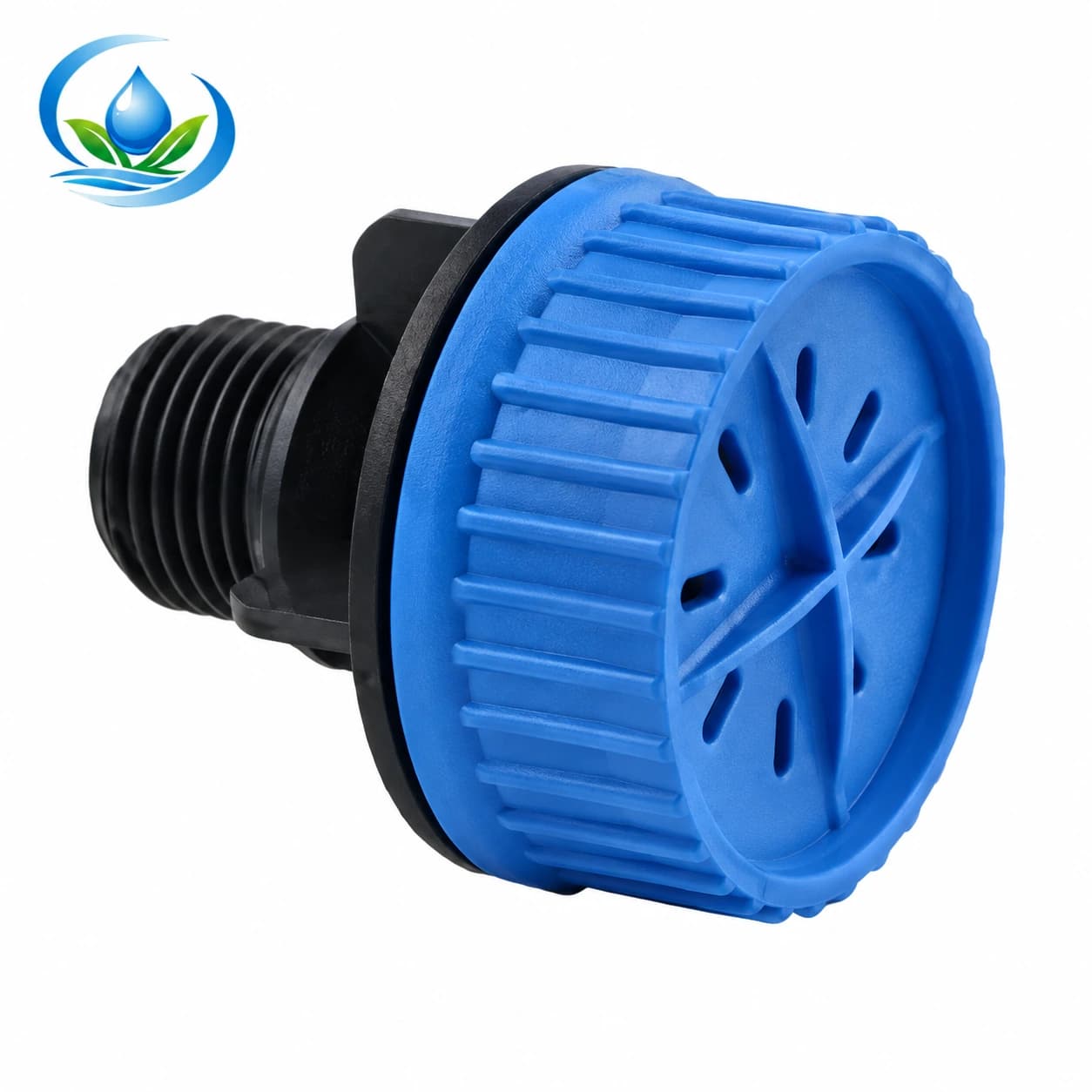
The male-thread flush valve has the listed EFV1/2M option with a nominal 1/2-inch male connection. It may be a candidate for a compatible, accessible threaded service point where the exact valve instructions and installation design establish its intended service function. Its name does not establish that it opens automatically as pressure falls, that it drains a particular low pocket, or that it protects a system from freezing. Confirm the female port's actual thread standard, sealing method, orientation, support and approved operation before ordering it.
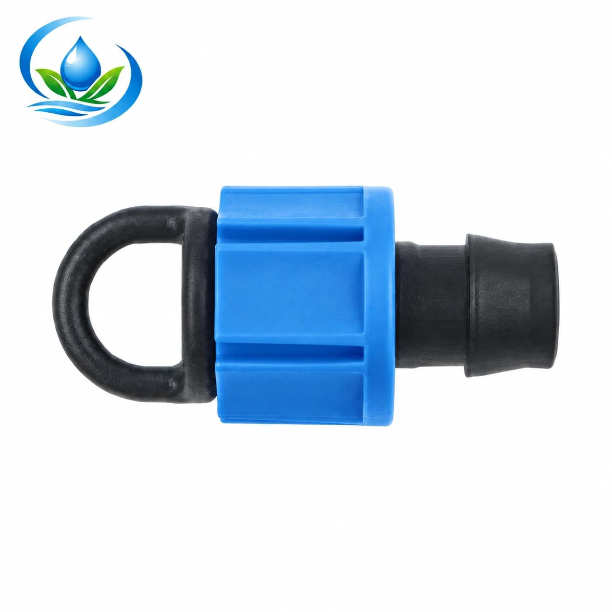
The lock-nut end cap offers TP0117 at nominal 16 mm and TP0120 at nominal 20 mm. It closes the end of a compatible line; reopening a verified end may support the system's approved service procedure. A cap does not create a drain below a sag and does not guarantee that a particular tape wall or round pipe will mate with its lock. Take the line model, sound sample or documented mating dimensions to the product comparison. A nominal diameter is a starting label, not proof of fit or a drainage specification.
The end fitting selection guide compares closures and flushable outlets by their connection job. This purchase adds a location test: is the proposed fitting at an approved outlet for the water-holding section, with an available permitted air path? A perfectly fitting cap at the highest row end cannot drain a low crossing. A threaded valve fitted into the wrong branch may be convenient to reach but irrelevant to the pocket you mapped. Give each intended fitting an identified section and purpose on the order list.
Where a new threaded adapter is proposed, document both mating ends and the required seal. The thread identification guide helps avoid treating a matching nominal size as proof of the same thread form. Do not force a binding thread or assume a valve photograph proves the needed connection. Permanent changes to a header or a device's drain port should be reviewed against its maker's instructions and the installed hydraulic design before parts are bought or a sound line is cut.
Finish with a verifiable field and purchase handoff
Give the next operator a section-by-section record: isolation and pressure verification completed under the site's procedure, known low points, documented access, components requiring separate service, observed drainage and unresolved pockets. Identify who will review each unresolved section. Do not label the entire system “empty” because the last visible drip stopped. Where freezing is the concern, the decision that an installation is adequately prepared belongs to the exact equipment and site plan; no fitting in this article carries a frost guarantee.
Make the parts list only after the map is settled. For each candidate, record section ID, outlet location, model or connection, intended function, mating item and quantity. Compare the selected product page's current price, sale unit, availability and delivery options. If the product has no suitable variant or the interface is unresolved, ask Store support about the exact product and site fit before ordering related pieces. The purchase may be no new end fitting at all if the actual low pocket belongs to an existing component's documented service route.
When the system is returned to service, follow its restart instructions and check any accessed closure or drain under the intended operating condition. Confirm that a service opening is closed or configured as its maker requires, and inspect for leaks before depending on the block for crop water. Keep the updated low-point drawing with the installation record. It will help the next crew distinguish a pressure-release task, a flowing debris flush, a seasonal parts inventory and the separate question that started this purchase: where does retained water in each section actually leave?
Before you order
Compare this guide with the specifications for your exact product, selected option, water supply and field conditions. Your equipment requirements take priority over a general example.
Compare irrigation products