Drip Irrigation Emitter Flow Is Uneven: Check the Pattern Before Replacing Parts
Map weak and strong outlets, collect equal-time samples under stable conditions, trace the shared or local fault, then choose the exact compatible replacement.
Published by IrriNex Store
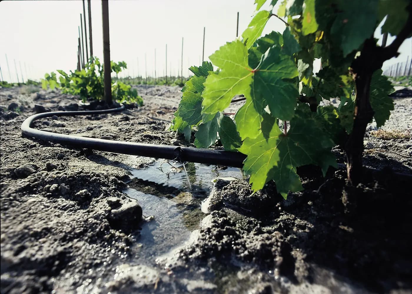
When drip irrigation emitter flow is uneven, mark where the weak and strong outlets are before buying replacements. A single low outlet beside normal neighbours suggests a different investigation from a whole row that weakens toward its end. A nursery branch that wets the supply-side tube but barely discharges at its stake is different again. Record the pattern while the normal zone is running; otherwise an attractive replacement part can leave the original fault in place. A drip emitter uneven flow test names each collection position and waits for the intended operating group to stabilize.
This guide is for an installed agricultural drip zone with accessible point emitters, remote microtube outlets, or inline emitters. It uses a small equal-time collection to screen a specific complaint and turns the result into a parts list only after the likely fault location is narrowed. It does not certify distribution uniformity for an entire field. Keep the selected model's instructions and the site's safe isolation procedure at hand.
Which emitter positions show uneven discharge?
Start at the valve and walk toward the end of the affected lateral. Give each suspect watering point a row, lateral and position identifier. Note which outlets are weak, excessive, stopped, leaking at the insertion hole or apparently normal. Draw the slope and mark high and low places. If an outlet feeds a separate tube and arrow, mark both the upstream metering point and the final discharge point.
Photograph the installed parts and their labels before touching them. Put an unused packaged example beside a suspect part if the original code is worn away; do not identify a flow option from colour alone. Record the number of open zones, the valve setting, filter condition and supply state. These details determine whether tomorrow's comparison is really the same test.
Look at the soil only as context. A dry surface can cover a wet root layer, while a wet mark may come from a leak or a different outlet. A plant's condition has many causes. Neither a dry patch nor a struggling plant proves that its emitter passage is blocked. The measurable question is whether the identified outlet delivers the expected flow under the conditions in which its neighbours are working.
Were the outlet samples collected after flow stabilized?
Open the zone as it normally operates and let the lines fill. Trapped air, an empty lateral and a remote branch filling for the first time can change the first moments of discharge. A line draining after the valve closes can leave lower outlets dripping longer. Note these startup and shutdown observations, but compare timed samples only after discharge and pressure have settled.
Use a container that can be supported without pulling a microtube, bending an emitter or changing the normal outlet height. Collect for the same elapsed time at every chosen point. Label each container before the trial. If water splashes away or the container interrupts the outlet, repeat that sample. Do not block another outlet with a thumb to make the suspect one look stronger.
Measure at least the positions needed to test the observed pattern: a suspect outlet and close like-for-like neighbours, plus relevant near, middle, far, high or low positions. The choice follows the complaint rather than a universal number of samples. Record the actual collection time and volume for each point, then convert with L/h = collected millilitres × 60 ÷ minutes ÷ 1,000. For example, 50 mL in five minutes equals 0.6 L/h; 200 mL in five minutes equals 2.4 L/h. These are arithmetic examples, not tested IrriNex results or acceptance limits.
Keep different rated flows in separate comparison groups. A 2 L/h outlet should not be judged weak because it delivers less than a neighbouring 8 L/h model. Similarly, an arrow supplied through a separate metering device may not be comparable with a direct point emitter. Write the full assembly beside each reading before deciding what “uneven” means.
Make a map that points to the next check
| Equal-time pattern | First checks | Parts decision |
|---|---|---|
| One weak outlet among like neighbours | Verify its code, connection, visible damage and local restriction; compare inlet conditions | Identify the individual replaceable part only if the fault remains local |
| Several weak outlets after one shared branch | Trace the shared valve, filter, feeder, tee and pressure at the branch | Resolve the common restriction before ordering a bag of emitters |
| Progressive decline toward a lateral end | Compare running pressure near and far; review total demand, length and elevation | Correct the hydraulic cause or line damage before selecting outlet replacements |
| Remote endpoint weak but upstream outlet appears normal | Inspect the microtube route, bends, connection and terminal device | Specify the exact branch component or tube if the restriction is there |
| Only startup or post-shutdown flow differs | Separate filling, air release and drainage from steady delivery | Repeat the stable catch before treating it as an emitter fault |
The table describes directions for investigation, not a diagnosis from a single symptom. One filter problem can coexist with a damaged outlet. A pressure difference can expose a non-compensating emitter's normal sensitivity while another outlet is genuinely blocked. Repeat the comparison after correcting each confirmed fault rather than changing several components together.
Trace a lone weak point from supply to discharge
For one low reading, compare the suspect with nearby outlets of the same identified model and rated flow during the same zone run. Check whether the body is cracked, poorly seated or leaking around its connection. If the outlet is remote, follow the tube along its entire supported route. A pinched tube under a container, a tight bend behind a stake or a partly detached connector can reduce useful delivery without an internal emitter clog.
Where the device's instructions allow a removable or cleanable part, follow that exact procedure after isolating the zone and relieving pressure. The product's appearance does not establish that it can be opened or cleaned. Do not push wire into a small passage, drill it wider or improvise acid or chlorine treatment. Those actions can change the metering path or create a safety problem while hiding the reason debris arrived.
If a clean, correctly connected outlet still reads low under comparable inlet conditions, set aside the exact part for identification. Match model, rated flow, inlet and outlet interface and any specified pressure behaviour. A larger nominal flow is not a repair for inadequate upstream pressure: it can overwater the repaired plant and raise demand for every other point on the zone.
Investigate shared and end-of-line patterns upstream
Several weak outlets beginning at the same tee suggest a shared route. Inspect the accessible branch, valve setting, supply tube and filter indicators. Measure running pressure at appropriate test points with a suitable gauge and compare it with earlier records and the selected product's instructions. If the whole zone has weakened, begin with the source, filter, regulator, valves and simultaneous demand before touching individual emitters.
When discharge fades progressively along a lateral, compare the first and last test positions while the usual number of outlets is running. Friction, elevation and excessive demand can reduce the available pressure toward the end; a partial obstruction or leak can change the picture too. Review the installed line's length and capacity alongside running pressure, and check for damage between the measured points. The field readings decide which cause warrants action.
A pressure-compensating emitter can help stabilise its own discharge only inside its documented operating range. It cannot raise a far-end pressure that is below the range, restore a blocked tube or protect a lateral from excess pressure. The running-pressure guide explains how to compare readings; the flow calculation guide helps check whether the active outlet count overburdens the zone.
For a dirty filter or repeated debris at emitters, review filtration and the manufacturer's flushing instructions before installing new parts. Filter selection guidance can help frame what information to gather about the water source and serviceable element. It cannot assign one universal mesh to every dripper. If a replacement clogs immediately at the same place, preserve that evidence and investigate the upstream path.
Separate an outlet from the tube that carries its water
A point emitter may discharge at the lateral, or it may meter water into a small tube that ends at a plant-side arrow or stake. Identify which component actually meters the flow. Collecting only at the terminal point tells you how the whole branch performs; it does not alone identify whether the emitter, tube or terminal is responsible. Compare a like branch, inspect the route and use only the approved service access for the assembly.
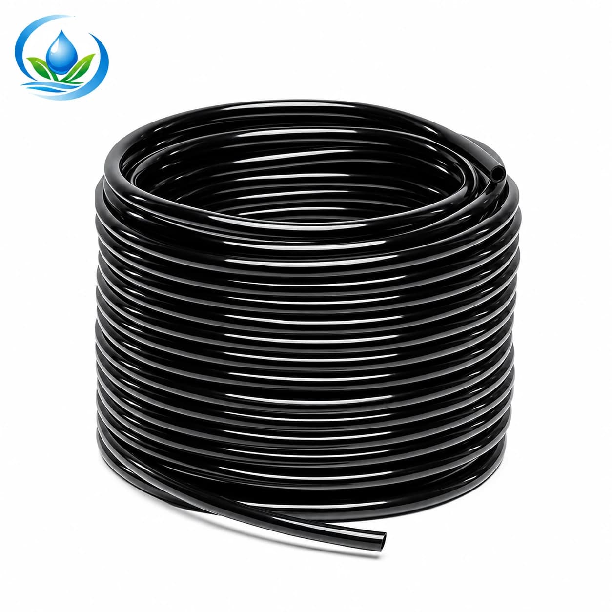
The micro distribution tube listing has separate 3 mm inside × 5 mm outside, 4 × 7 mm and 8 × 11 mm variants. Inside and outside diameters serve different connection questions. A visually similar tube may not seal on the existing barb, and a longer or kinked route may alter delivery. Take both dimensions and the existing connector identity to the product page before buying a replacement length.
If a remote outlet is strong while adjacent terminal outlets are low, do not assume the one strong branch is correct. It may use a different metering component, a disconnected restriction or a leak. Record every branch's parts and compare it only with branches built the same way. The nursery endpoint guide explains how to distinguish an arrow, holder and upstream meter when assembling a repeatable pot connection.
Identify the exact replacement family and variant
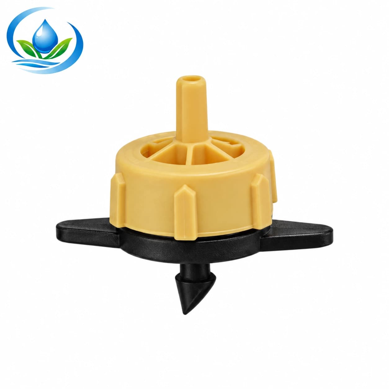
The IrriNex pressure-compensating dripper family has three distinct nominal choices: TANDPCD02 identifies the 2 L/h option; the 4 L/h choice is TANDPCD04; and TANDPCD08 denotes 8 L/h. The catalogue confirms these labels. Confirm the selected option, working conditions and connection against the current product page and installed part. A family description does not make its variants interchangeable, and the flow label is not a measured promise outside the specified conditions.
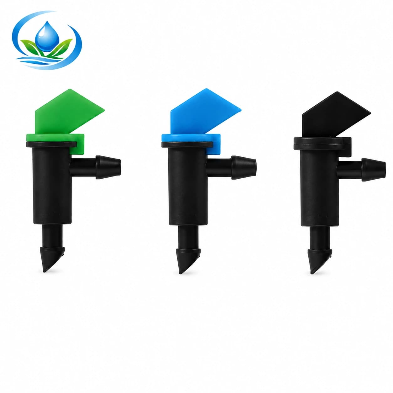
The flag-style on-line dripper listing includes FD04, FD08 and FD16, labelled 4, 8 and 16 L/h. These are different discharge options; the listing does not establish pressure compensation for this family. An outlet that resembles an FD08 should not be ordered as FD08 on shape alone. Read the part marking, retained package or original order and confirm the inlet and service method before replacing it.
Where the weak point is built into an inline drip pipe, it may be part of the factory-made lateral rather than a separately removable button. Identify the exact pipe variant, outlet spacing and affected section, then obtain the approved repair method and compatible connectors. Pulling at an integral outlet can damage a sound line. If the line section must be replaced, plan the cut and connection only after the zone is isolated and depressurised.
Check quantity against the map. Three weak outlets on one blocked branch do not automatically require three emitters. Conversely, one cracked body may need an emitter plus a correctly sized connection repair. Prepare a purchase list from named parts, selected variant and supported fit; check the current pack quantity, price, availability and ordering options on each product page.
Retest the marked positions after each repair
Close the supply and relieve pressure before disconnecting or cutting a part. Keep the removed component labelled by its map position. Install the approved matching replacement without enlarging a lateral hole or forcing a tube onto an uncertain barb. Restore the normal end closures and valve arrangement, inspect for leaks, then let the zone reach steady operation again.
Repeat the same timed collections at the repaired point and its original comparison neighbours. Include the far or shared-branch reference if that was part of the first pattern. Record the second volumes, operating pressure and filter condition alongside the first. If the low reading persists at the same location, the new emitter was not the full explanation. If it moves to another location, check the common supply and differences between branches.
Accept the repair against the selected component's documented performance, your site's baseline and the crop's intended delivery; this short screen provides no universal allowable percentage. A repaired emitter with a correct catch may still leave the plant's wetted root area wrong, so assess moisture and placement separately. If changing rated flow or outlet count was intentional, recalculate the watering event with the post-change runtime worksheet.
Use the record to select a replacement
Bring the lateral and position map, photographs of the part and its connections, the exact code or labelled old package, timed volumes, running pressure where measured, and the number of affected locations. For a microtube branch include both tube diameters and the terminal component. For inline pipe include its printed specification and spacing. This record turns “some drippers are weak” into a specific replacement choice.
If a needed specification is missing or the selected option cannot be ordered, send that record to IrriNex Store support before choosing a substitute. Recheck pack size, price and availability when ordering. Keep the accepted component code with the zone log so the next uneven-flow complaint can be compared with an actual baseline rather than a remembered colour or wet patch.
Before you order
Compare this guide with the specifications for your exact product, selected option, water supply and field conditions. Your equipment requirements take priority over a general example.
Compare irrigation products