Emitters for Drip Irrigation: Identify the Inlet and Outlet
Two similar stems can be an emitter inlet and outlet. Confirm the exact water path, tube connection and model before ordering nursery replacements.
Published by IrriNex Store
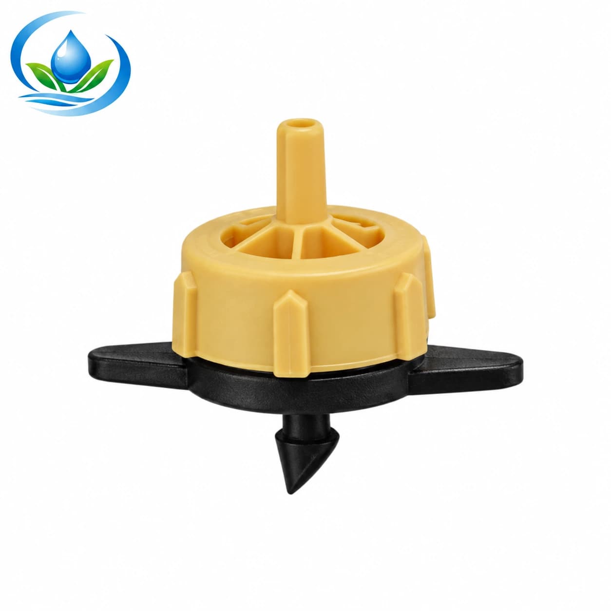
Emitters for drip irrigation need an identified supply connection and an identified discharge connection before they are fitted to a crop line. Two small stems on a button dripper may look alike while serving different purposes. If a replacement is pushed into the lateral by its outlet, or a delivery tube is forced onto an unverified stem, the resulting leak does not prove that the grower needs a higher-flow emitter. Establish the water path and the exact mating parts first. Draw supply-to-plant arrows beside the exact emitter connection drawing and tube code; similar-looking barbs cannot establish water direction. Drip emitter inlet and outlet direction belongs on the connection sketch before matching or cutting microtube.
Consider a nursery replacing several damaged drippers beside a greenhouse bench. The order record identifies the nominal flow, but a bag of loose parts has no assembly drawing. One installer expects the small tube to feed the dripper; another expects it to carry water away from it. Before ordering a whole bench of replacements, mark the source side and the plant side on one complete, identified example. That small connection record determines which emitter version, tube size and supporting parts the nursery actually needs.
Which stem is the drip emitter inlet and which is its outlet?
Start at the pressurized supply and follow one intact branch to its final watering point. Draw the lateral, any plain take-off connector, the small tube, the emitter body and the terminal outlet in the order encountered. Record the installed model at each connection. Water entering a metering body belongs at that body's documented inlet; water leaving it uses the documented outlet. A photograph labelled only “top” and “bottom” becomes ambiguous when the device is turned in the hand or installed beside a vertical support.
There are different arrangements to identify. A verified emitter can sit directly in an approved supply-pipe opening and discharge through a separate delivery tube. Another documented arrangement may place a compatible emitter at the far end of a supply microtube. Those layouts put the tube on different sides of the metering body. They are alternatives to check against the exact manufacturer's instructions, not permission to move every emitter between both positions. Record the existing arrangement before deciding whether the replacement will preserve it.
Keep an ordinary connector separate from an emitter. A double-ended connector can join a tube without metering its discharge. A small body with two visible connections may contain a metering passage that expects a particular flow direction. Neither the number of stems nor the fact that a tube can be pushed over one proves its function. The nursery endpoint guide helps identify the plant-side arrow and upstream metering component; this check labels the inlet and outlet of the actual dripper between them.
Does microtube feed the emitter or carry its discharge?
Read the marking on a complete unused example, its original package and the previous purchase record. Photograph both sides with the model code visible. Ask the supplier to identify the water inlet, the water outlet, the permitted connection on each side and the installation instructions for that exact version. If the old part is unmarked, retain it as an unidentified sample. Do not promote a remembered colour or the sharpness of one barb into a confirmed installation direction.
Manufacturers can offer a single emitter family with several discharge interfaces, such as a straight barb, an angled barb or a connection intended for a separate assembly. The selected version matters even when the nominal flow is unchanged. An illustration for one outlet version cannot certify another one, and an inlet that fits a prepared pipe wall does not automatically accept the same tube as the outlet. Keep each dimension attached to the named interface it describes.
A useful seller response annotates the precise supplied model. It states which side receives pressure, what can connect to the other side and whether an adapter is needed. A generic photo of a similar emitter is incomplete evidence. If a product page gives discharge choices but omits its interface drawing, resolve that omission before making holes or cutting a large quantity of microtube. The emitter selection guide handles nominal output and pressure behaviour; neither specification establishes the shape of the mating connection.
Keep the Store emitter and tube labels separate
The listed pressure-compensating emitter family has three catalogue choices: TANDPCD02 is labelled 2 L/h, TANDPCD04 is labelled 4 L/h, and TANDPCD08 is labelled 8 L/h. These codes identify nominal flow options. The original catalogue table does not provide an annotated inlet/outlet drawing, an insertion-hole requirement or a verified tube pairing. It therefore cannot answer which stem should accept a particular microtube merely by showing the dripper's appearance.
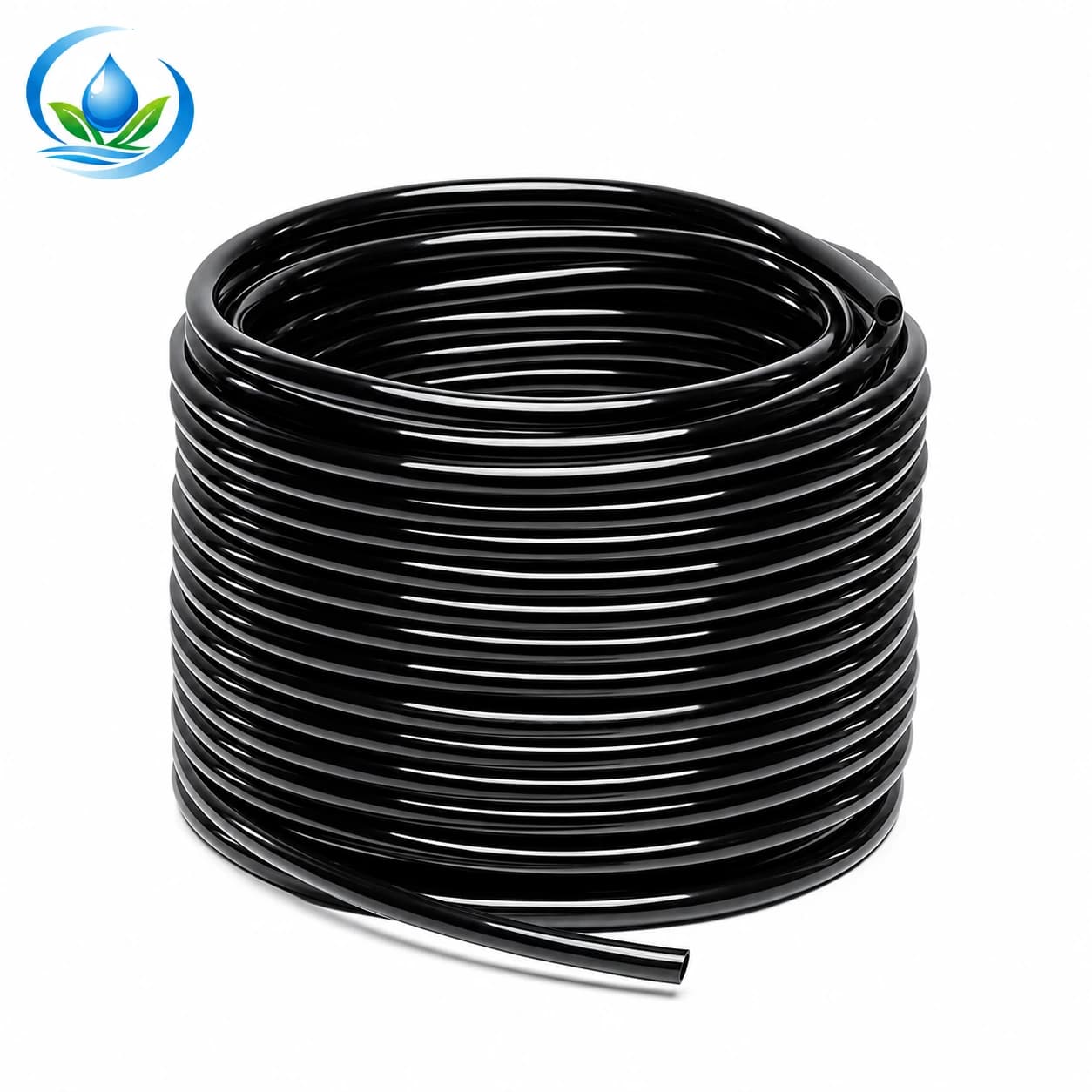
The micro distribution tubing listing offers paired dimensions of 3 mm inside by 5 mm outside, 4 mm inside by 7 mm outside, and 8 mm inside by 11 mm outside. The two numbers describe one tube's bore and exterior. They do not describe the emitter's two stems. Select a tube only after its material and dimensional pairing have been approved for the identified connection. The catalogue does not establish that every one of these tube options fits any TANDPCD variant.
For example, an enquiry can name the existing TANDPCD04 flow code and ask whether the proposed delivery tube belongs on its outlet, which exact tube dimensions are supported there, and whether another piece is required. That is a specific compatibility question. Writing “4 L/h, therefore 4 mm tube” would confuse discharge with diameter. Likewise, a 3/5 mm tube label gives no authority to prepare a 3 mm or 5 mm hole in the supply pipe. The required opening belongs to the particular inlet and pipe combination.
Confirm operating conditions independently. An accepted tube-to-outlet connection does not prove that the emitter can operate at the available inlet pressure, feed a long rising tube or provide the planned water at a remote endpoint. Keep the complete arrangement's permitted duty with the supplier's answer. Do not borrow another manufacturer's pressure range, filter grade, anti-drain claim or service procedure simply because its button dripper looks similar.
Distinguish a pipe opening from an open tube end
A stem inserted into a prepared lateral wall meets a different interface from a stem fitted inside the open end of microtube. For the wall connection, document the supply-pipe material, wall, approved hole and inlet geometry. For an open tube end, document the tube bore, exterior, material and the named stem it will cover. Keep those two rows on the order sheet even when they occur on opposite sides of one small emitter.
The pipe-punch preparation guide explains how to confirm a supported tool, opening and pipe combination. Do not start that preparation while the inlet is still unidentified. Avoid trying alternate ends of an unknown emitter repeatedly in the same hole: repeated removal can leave damage that disguises the original connection mistake. An enlarged or torn opening needs its own approved repair decision after the supply has been isolated and pressure relieved.
For the microtube, inspect an identifiable sound sample and retain its dimensions with the part code. An old stretched end may appear to accept a stem that fresh tube will not. Do not use that distorted end as a sizing gauge or force the connection with heat, oil or a modified barb. Obtain the chosen product's permitted preparation and assembly method. If the tube only reaches by pulling sideways on the dripper, correct the route and support before accepting the pairing.
Make one documented trial without changing the crop plan
Once the exact interfaces are confirmed, assemble one representative connection by the maker's instructions on a safely isolated and depressurized section. Keep the inlet/outlet drawing beside the actual parts and compare the delivered model with the order. Protect openings from soil while working and perform the prescribed debris-clearing steps. Restore the existing filtration, regulation and other required protection before observing normal operation. Removing protective equipment is not part of this connection check.
Run the intended operating group within the documented limits and observe the supply-wall connection, the emitter body, the tube connection and the final outlet separately. A drop running along the outside of a tube is different from water travelling through its bore. Trace where an observed leak begins without handling or opening a live joint. If the connection fails, isolate again before inspection; do not squeeze it shut with a hand to create an apparent pass.
Confirm that the plant-side endpoint delivers water under the unchanged arrangement. Use a supported timed collection where appropriate, keeping the outlet at its intended position and avoiding a kink or added load. A correctly facing emitter can still have a restricted downstream tube or inadequate supply. The uneven-discharge guide separates those broader fault patterns. Here, the trial verifies that the identified interface arrangement fits and operates; visible dripping alone is not proof of the nominal litres per hour.
Keep an unsuccessful sample labelled until the cause is resolved. Record whether the discrepancy was the delivered model, the interface drawing, damaged pipe, an unsupported tube size or another operating fault. If the supplier changes the outlet version or proposes an adapter, update the drawing and trial that documented combination. A different connection should not enter the accepted batch under the old sample's name.
Order and hand over an identifiable assembly
The order should name the complete emitter variant and quantity, the confirmed inlet arrangement, the exact outlet version, the approved tube dimensions and the measured routed length. List any separately required adapter or support rather than assuming it comes with a photographed dripper. Count trial pieces and replacement stock separately from outlets that will operate together. The parts list should preserve the established crop-flow choice instead of quietly replacing every uncertain connection with a higher-output model.
Check the current product page for the selected option, price, sale unit, supply status and delivery terms. If direct ordering is unavailable, send Store support the annotated old assembly, its code and the unresolved interface question. Ask for confirmation against the product that will actually be supplied. The useful answer connects two named parts; “it fits drip tubing” is too broad to approve a whole nursery order.
At delivery, compare labels and interfaces before distributing loose pieces to the crew. The delivery inspection guide covers the wider receipt check. Keep one accepted sample or an annotated photograph with the installation bundle, showing the direction from supply to plant. If a worker encounters another body shape, tube dimension or missing code, pause that location and identify the difference. An inlet/outlet record makes the next replacement a repeatable parts choice instead of another trial with two similar-looking stems.
Before you order
Compare this guide with the specifications for your exact product, selected option, water supply and field conditions. Your equipment requirements take priority over a general example.
Compare irrigation products