Drip Irrigation Soaker Hose: Identify the Old Line Before Replacing It
Identify porous hose versus factory-emitter line, inspect inherited connections and treatment, and decide what to retain before buying a replacement.
Published by IrriNex Store
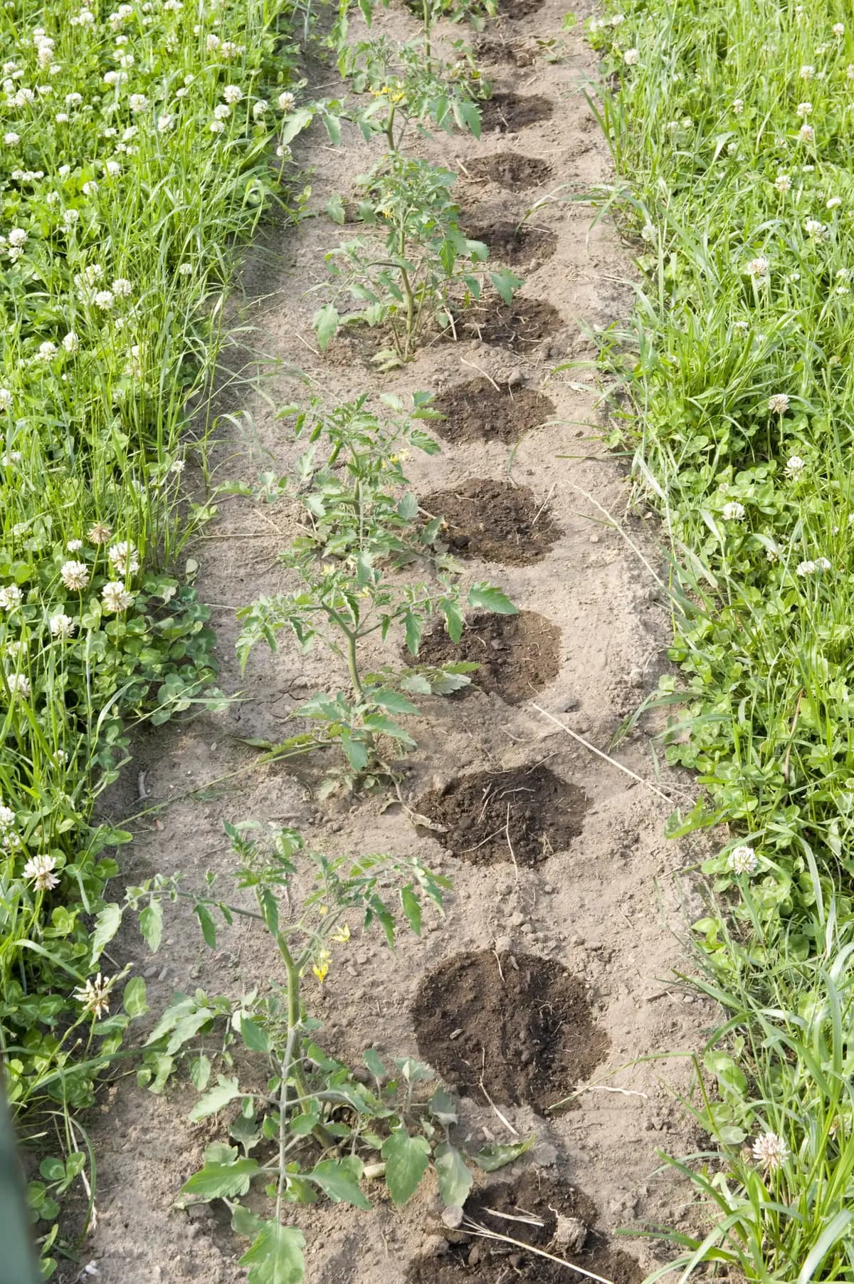
A drip irrigation soaker hose replacement starts with identifying the line already in the crop bed. The word “soaker” may describe a porous hose that releases water through its wall, or a small dripline with manufactured outlets. Those constructions create different replacement questions. Before reusing the old connectors or controller settings, establish what is installed and which parts of its supply arrangement the new line actually requires.
This guide is for an existing agricultural bed or crop row where the watering line needs replacement or a change of format. It leads to a retain, replace or verify decision for the inherited parts. It does not assume that every old hose should be converted, or that a new emitting line includes the connections and treatment equipment needed to make that conversion work.
Identify the old soaker-like line before choosing a replacement
Look for the original label, purchase record or model marking. Inspect an accessible, clean section with the system isolated. Note whether there are repeated outlet positions, visible internal emitter shapes, a porous wall or another construction. A black surface, a flexible feel or a hose-style end connection is not enough to establish the product type. A soaker hose to inline dripline replacement should separate the old emitting section from any sound non-emitting feed that can remain.
The FAO handbook on pressurized irrigation distinguishes porous-wall pipes from drip tape with manufactured emission points. That distinction identifies how water leaves the line; it does not supply a universal pressure setting for an unidentified hose.
If the old product still operates and a supervised observation is appropriate, compare where water appears along an undamaged section. Discrete leaks from cracks should not be mistaken for factory outlets. Conversely, an emitting line partly covered in soil may not reveal its outlet pattern immediately. Keep its identity unresolved until the label, construction or supplier information supports the conclusion.
Record why replacement became necessary
Write the observed problem before choosing its remedy: a split wall, leaking factory end, uneven wetting, recurring blockage or an incompatible planting pattern. Include the location and operating arrangement. Replacing the lateral may address a damaged wall, but it will not automatically correct a restricted supply or an existing filter problem.
Photograph the route and connections before dismantling them. Record installed length, curves, slopes, number of branches and the beds operating together. Preserve the old schedule as a labelled historical setting. It describes what was programmed, not proof that the old installation delivered the right water volume.
If the hose is damaged, do not treat its current discharge as a healthy baseline. A substantial leak can increase measured inlet flow while leaving the far end short of water. Keep observations of the fault separate from any earlier reliable measurements so that the replacement is not selected to reproduce a defective operating condition.
Trace the inherited assembly before discarding small parts
Follow the route from the supply connection to the lateral. Identify source protection, timer, filter, pressure-control device, adapters, blank feed, branch fittings and terminal closure. Record the model on each part and photograph the order. This inventory concerns what actually exists, including pieces whose function is not obvious from the outside.
Some assemblies contain a flow-limiting insert, a screened washer or another small component inside a connection. Do not assume every insert has the same purpose or remove it merely because a new line appears to need more water. Establish its identity and the assembly instructions before deciding whether it remains part of the replacement arrangement.
Mark unidentified items as awaiting verification. A device that fitted the old hose is not automatically needed by the new lateral, but neither is it automatically redundant. Keep required source protection in place and resolve the actual functions before ordering a different sequence of components.
Inspect the joint where old feed meets new dripline
Inspect both sides of the proposed transition. An old hose can finish in a swivel connector sealing against a washer, while the new tube may require a metric barb, a locking tape fitting or another connection. The printed nominal sizes alone do not establish a mating pair.
Record the thread standard, male or female form and intended sealing surface where a threaded connection is involved. Identify the tube dimensions and the fitting's permitted tube construction on the other side. A connector that starts turning is not proof that its thread matches. Extra sealing material cannot turn the wrong interface into a supported conversion.
Measure sound tube rather than a crushed or expanded end. Check for cracks, missing seals and damage from previous removal. A retained fitting must be both compatible with the new arrangement and serviceable in its own right. If either remains uncertain, hold that joint out of the accepted parts list.
Decide whether the non-emitting feed can remain
The feed between the source equipment and the crop lateral may be a separate piece worth retaining. Identify it independently of the hose being removed. A sound, correctly sized transport line does not become unsuitable merely because the emitting section changes, but its connections and capacity still need checking for the new operating demand.
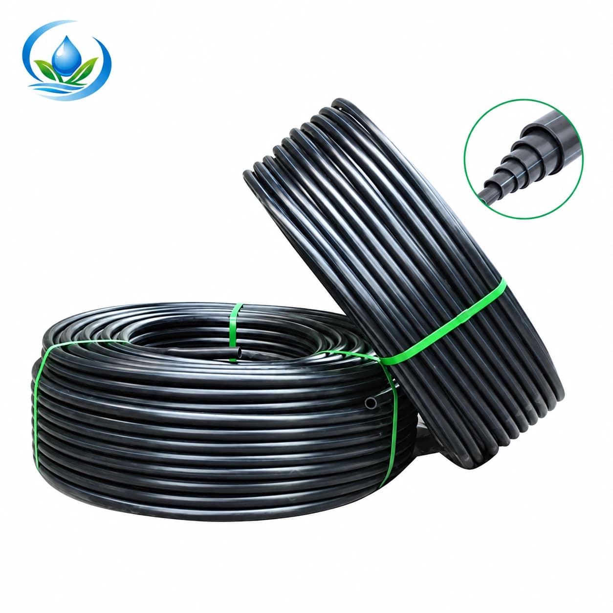
For a replacement transport option, the blank PE tubing listing includes IS-4-DD62380CF7. Its wall is 1.0 mm and its outside diameter is 16 mm. It has no built-in outlets. These dimensions identify a candidate feed; they do not approve the old hose connectors or establish capacity for an entire block.
Label the retained feed and replaced lateral separately on the drawing. Include the supply distance through a path or along a bed end. That transport section should not become an emitting section by accident. Where its route, condition or capacity cannot be established, request the missing evidence before counting it as a saving in the order.
Specify an inline replacement without inheriting old performance
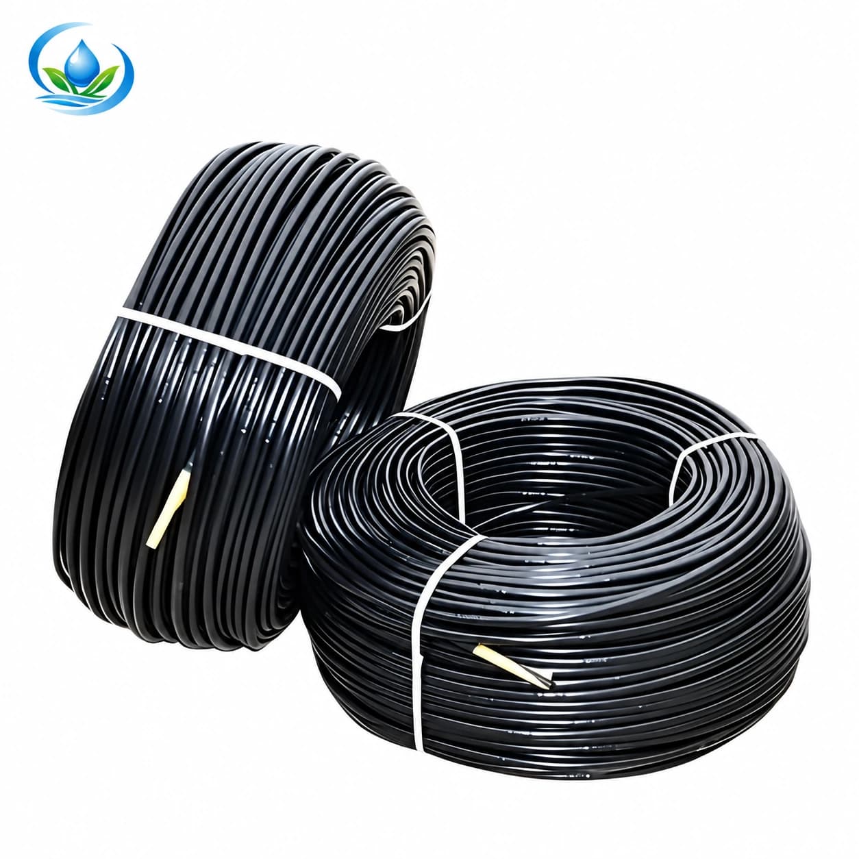
The inline dripline variant IS-3-8CDA6B18CD has a 0.8 mm wall around its 16 mm diameter, with factory outlets at 30 cm intervals. It is listed as a 2 L/h emitter option supplied on a 500 m roll. Preserve the complete variant when discussing a replacement.
These are identification and nominal-discharge details, not a measured result from your existing system. Obtain the operating conditions, filtration requirement and permitted lateral layout for that exact option. Its name does not establish pressure compensation, permanent burial suitability or that 500 m may operate as one continuous run.
Compare the proposed outlet positions with the crop area formerly served by the hose. Matching the old installed length does not necessarily reproduce its wetting pattern. If the old route curls tightly around obstacles, assess the new tube's permitted bends and support rather than forcing it into every turn left by the removed hose.
Keep a tape conversion tied to its own fittings and data
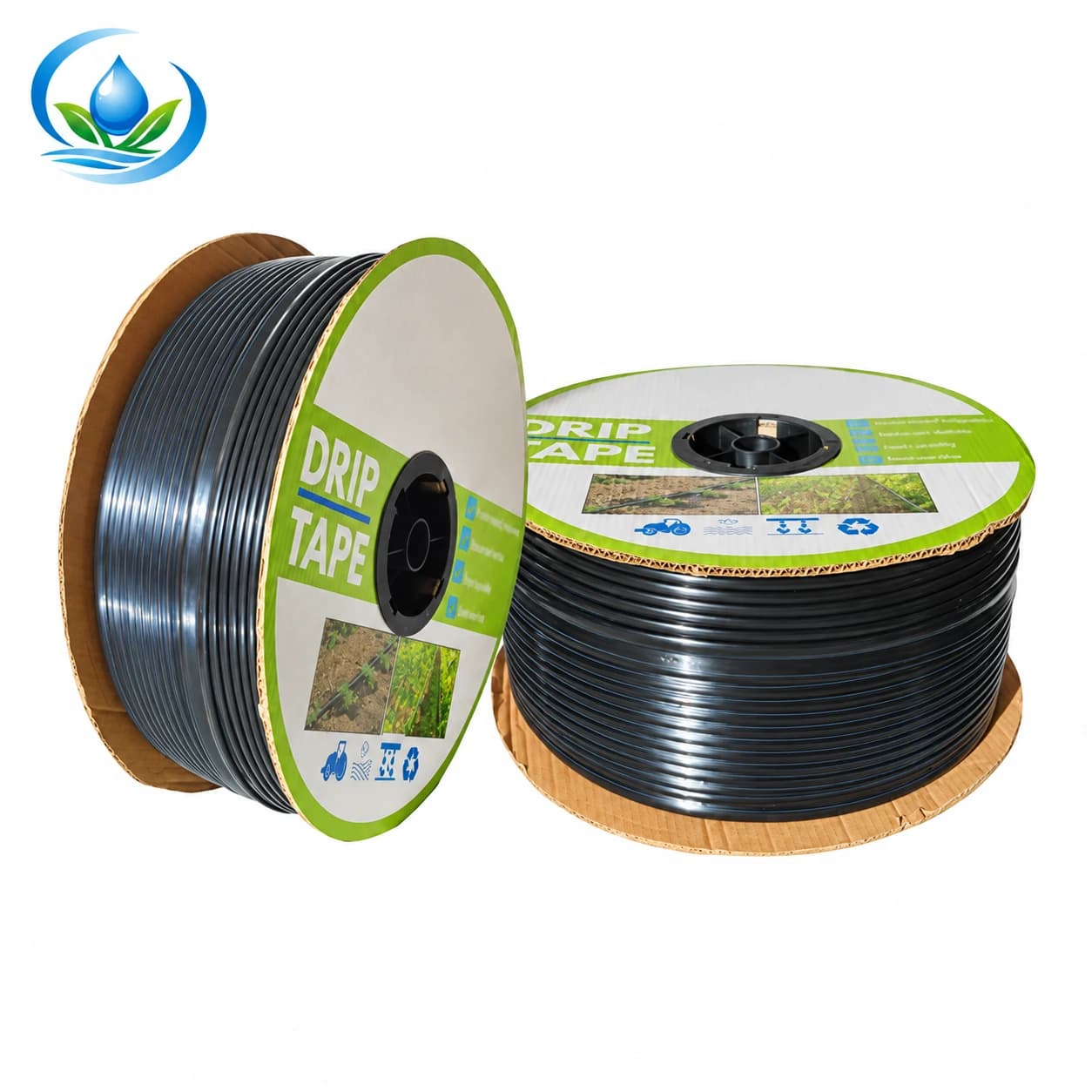
A candidate from the flat-emitter drip tape range is IS-2-C526AC2D85. This option combines a 2,000 m roll with 30 cm outlet spacing; its tube diameter is 16 mm and the wall measures 0.2 mm. The roll is a purchasing quantity, not evidence that a long inherited hose route suits one tape lateral.
The dimensional configuration does not supply a verified discharge for that exact option. Obtain its flow basis and pressure limits before calculating the new demand or accepting an old regulator. Do not borrow a figure from another tape spacing or treat a general family statement as the specification of the selected roll.
Identify tape-specific starts, retention and ends as a complete connection question. Existing hose-threaded ends are not automatically transferable, and an ordinary round-tube barb is not an assumed tape fitting. If the selected tape cannot follow the old route under its instructions, revise the layout before buying rather than promising a direct swap.
Reassess the filter that the old hose used
Record the installed filter model, its element and the water it treats. A screen visible inside a hose connector may have a different role from the filtration required by the replacement's small passages. Appearance alone cannot establish a suitable filtration grade or capacity.
Compare the new outlet requirement with the fitted element, the intended simultaneous flow and the expected pressure loss. Include access for inspection and cleaning. A filter housing that appears serviceable may still need a confirmed element or may not support the new duty; those are different decisions from replacing every part.
The filtration selection guide explains the broader choice. For this replacement, record a specific result: retain the identified assembly when supported, change the confirmed incompatible item, or pause that part of the order pending its documentation.
Check pressure control and the timer separately
Identify whether the existing pressure-control part regulates pressure under stated conditions or simply restricts flow. A remembered tap position does not establish the downstream operating pressure of a replacement line. Record pressure during the proposed flow condition and compare it with each component's documented limits.
Review the regulator's minimum and maximum flow as well as its pressure requirements. Fewer outlets or a different discharge can move the installation away from its former operating case. The pressure-regulator guide helps distinguish a matching regulator from a part retained only because it was already there.
Check the timer's valve requirements and normal stopping behavior independently. A working display or clock does not demonstrate that the valve will operate under the changed hydraulic conditions. Preserve the model information and instructions before enabling a new automatic program.
Calculate the new demand for the same identified crop group
List the replacement's installed emitting length and actual active outlet count or its documented flow-per-length basis. Include only branches that will run simultaneously. Porous hose cannot be assigned an emitter count from an assumed spacing; observations or model data for that hose belong in a separate old-system record.
Compare the new demand with the supply, retained pipe, filter and controls. The flow calculation guide covers the arithmetic. Keep the same crop-group reference in the comparison so that changing both equipment and open-bed count does not hide the reason demand changed.
A successful one-line sample does not establish that all replacement rows may run together. Conversely, buying a large roll does not require all of it to operate at once. Record the intended valve combination and check the whole group before accepting the retained supply equipment for that duty.
Try the actual transition before replacing every row
With the system isolated and pressure released, assemble a representative connection using the intended old and new pieces. Follow their specified insertion, locking and sealing methods. Do not trim an unknown fitting or stretch tubing to make a nearly matching combination look acceptable.
Flush the retained delivery path and new lateral as their instructions require, then observe a controlled operating trial with the normal protection equipment installed. Inspect the old-to-new transition for leakage, movement and strain. Leave it accessible while the trial is being assessed.
Measure the replacement at representative positions under comparable conditions. A total meter reading can include leakage or an unintended open branch, so check distribution as well as supply flow. Keep sample locations and active valves with the readings, allowing another person to repeat the test after a correction.
Recheck the wetting pattern before restoring old minutes
Inspect moisture where the crop's roots need it, including positions between new outlets and near the ends of the served area. Record initial conditions and observations after a defined trial. A line that seals correctly can still place its outlets poorly for the crop or leave gaps that the previous arrangement did not have.
Do not restore the old timer duration merely because the replacement has the same overall length. The delivery rate and the locations where water enters the soil may have changed. Use the runtime review after emitter changes to assess that separate scheduling decision once the hardware is operating properly.
If near outlets receive enough water while the far end remains weak, investigate the distribution before simply adding minutes. Longer operation can increase water at already wet positions without resolving an incompatible component or restricted route. Record the fault and retest the affected arrangement after correction.
Finish with a replacement record that names retained parts
For each inherited component, write its identity, condition, compatibility evidence and decision. “Retain” should mean that the part has a documented job in the new assembly and passed the relevant check. “Replace” should name the actual incompatible or damaged part. “Verify” should identify the missing model, dimension or operating information.
Confirm sale units, selected variants, quantities and supply terms for the items being purchased. Keep the old label or a useful photograph with the replacement model and accepted test readings. This prevents the next operator from identifying the new line only by the same ambiguous hose name.
Send the old connection photographs, measured route, component labels and proposed replacement through IrriNex Store support when a particular interface remains unclear. The useful outcome is a justified list of what stays and what changes, followed by a measured installation whose delivery and schedule have been checked again.
Before you order
Compare this guide with the specifications for your exact product, selected option, water supply and field conditions. Your equipment requirements take priority over a general example.
Compare irrigation products