Irrigation Water Filter: Check the Sand Separator Collection Chamber
Before replacing a sand separator or downstream filter, check the collector's service record, approved discharge path and actual operating flow.
Published by IrriNex Store
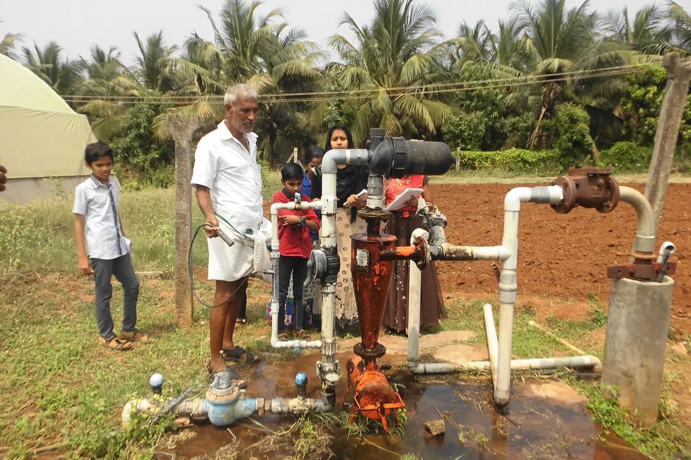
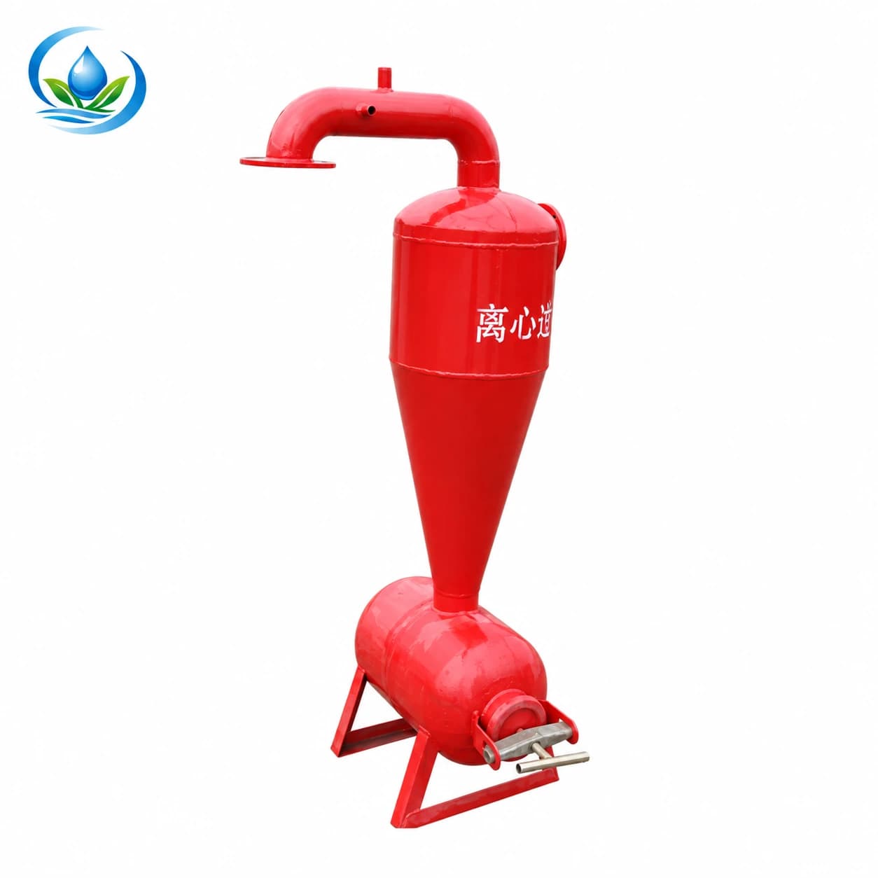
An irrigation water filter can load with sand even when a separator is installed ahead of it. Before ordering a larger filter or replacing the separator, identify what happens to the material collected at the bottom of that separator. A chamber that is no longer being emptied, an obstructed discharge route or operation outside the model's stated flow range needs a different response from a damaged disc element. Start with the installed model, its service instructions and a record of the actual operating condition. A cone-shaped housing alone does not establish that sand is being removed successfully. Pair the observed chamber condition with the verified purge destination and actual running flow; changing a downstream disc filter cannot empty the upstream collector. Hydrocyclone sand chamber purge needs a verified collection state and an approved discharge destination, not a guess from a downstream filter.
This guide concerns an existing agricultural hydrocyclone and its sediment collection arrangement. It is a practical service-and-purchase check, not a universal flushing procedure. Agriculture Victoria's filtration guidance distinguishes centrifugal sand separation from the final filtration protecting drip equipment. Keep that distinction when investigating the installation: removing collected grit is one job, cleaning a downstream element is another, and neither action establishes that dissolved-water problems have been treated.
Is the hydrocyclone sand collection chamber full?
Record the separator maker, model, inlet and outlet markings, collection chamber and the connection identified for purge or sediment discharge. Photograph the complete installed route from a safe position. Include the final filter, normal crop outlet, drain destination and the controls named in the approved operating procedure. A valve near the bottom might serve the intended purge route, but its position is not enough to identify its function. Find the equipment drawing before treating an unfamiliar handle as a cleaning control.
Distinguish a sand separator from a sand-media vessel. The separator removes suitable heavier particles from moving water and gathers them for discharge. A media vessel contains a specified filtering bed with its own cleaning arrangement. Do not add filter sand to a hydrocyclone collector, or adopt a media-filter reverse-flow sequence because both products have “sand” in their names. The media-filter backwash guide applies to the separate vessel-and-bed decision, rather than instructions for this collector.
Check the service record as carefully as the hardware label. When was sediment last discharged under the model's instructions? Which zone was running, who observed the outlet, and was the normal valve state restored afterward? A tick beside “filter cleaned” may describe only the downstream disc stack. Name the actual component in the next entry so one person's filter cleaning is not mistaken for another person's separator service. Where the history is unknown, record that uncertainty instead of estimating an interval from the age of the installation.
Where does the approved separator purge discharge?
Write down the operating group that produced the symptom. Include the running flow where it can be measured by an approved method, the available pressure readings and any recent change in open crop blocks. A separator selected for one flow case may need reassessment when fewer or more rows run together. Its recommended working range must come from that exact model. Matching the inlet pipe diameter, or seeing water at the crop outlet, is not proof that the separator is working within that range.
Do not use a downstream filter's pressure differential as a direct measurement of how full the separator chamber is. Identify where each gauge connects and which component lies between the readings. The downstream element may be loading while the separator's collector also needs attention, or the observed material may require a different treatment stage. The screen-filter service guide addresses the element and housing separately. Keep the observations paired with their measurement locations so an ambiguous gauge reading does not trigger the wrong replacement.
Consider the source condition recorded when trouble began: well startup, a different supply, an intake change or a particular zone combination. Describe visible material without assigning it an unmeasured particle size or removal percentage. A gritty discharge is evidence of material at that outlet; a clear-looking discharge is not proof that all relevant particles have been removed. The water-test reading guide is the next reference if the contaminant itself is uncertain. This collector check does not replace representative source analysis.
Check that the approved purge has somewhere to go
Trace the installed purge route all the way to its receiving point. Record any hose, valve, elbow, change of level or shared connection visible along it. Look for an outlet that has become buried, a hose folded by stored equipment or a collection area no longer accessible to the operator. These are observations to compare with the model's approved arrangement, not permission to disconnect an operating line. Keep the dirty discharge away from the clean crop manifold and from clean parts awaiting reassembly.
Ask the equipment supplier to confirm the required discharge condition if the route has been altered since installation. The inlet connection size does not specify a suitable purge pipe, and a drain that accepts ordinary water may behave differently when it carries settled solids. Show the actual route, length, elevation changes and receiving condition in the request. Avoid installing an improvised restriction or tying the outlet into another pressurized line simply because the fittings can be joined. Resolve that proposed connection against the separator's own documentation.
Separate routine operation of an identified purge valve from opening a collection cover or removing pipework. Some designs provide an operating purge, while intrusive cleaning requires a different service state. Use the exact model's procedure and the site's isolation controls; a stopped pump alone does not establish that a chamber is depressurized. The planned line-work isolation guide helps document the relevant sources and controls. Never loosen a pressure-containing cover to discover whether sand is inside.
Record the result before choosing a replacement
Have the responsible operator carry out only the purge or inspection authorized for the installed equipment. Record the date, operating group, observed discharge, apparent obstruction and the normal state restored afterward. Keep the observer out of the discharge path. The article supplies no universal number of seconds, daily frequency or valve-opening amount: those settings depend on the model, its collector and the loading experienced at this installation. If the approved operation does not produce the expected discharge, stop and obtain the specified service method rather than forcing a handle or cover.
Describe the result using separate observations. For example, “no discharge at the designated outlet during the approved check” is more useful than “bad filter.” “Discharge occurred but the downstream element loaded again in the same crop group” describes a different finding. Preserve any relevant photographs and the equipment's stated acceptance criteria. Neither observation alone identifies which internal part has failed. It may justify checking a blocked path, the operating range, the water source or the final element before choosing a complete new separator.
If the model requires isolated collector cleaning after sediment has compacted, follow its documented procedure or arrange suitable service. Obtain the exact seal, cover and valve information before disassembly if those parts may be needed. A replacement seal that resembles the old one can still have the wrong profile or material. Do not assume the Store supplies an individual chamber cover or repair kit just because another manufacturer's separator offers one. A parts request should name the installed maker and model and include the relevant drawing or part reference.
After permitted service, compare the same operating group and observation points with the earlier record. Note whether the approved discharge route now works and whether downstream loading has changed. Keep the final filter in service as designed throughout normal crop irrigation. Removing its element to make the pressure reading improve would expose the crop outlets and make the comparison meaningless. The disc-stack return-to-service guide covers that separate element check when the downstream device also needs attention.
Compare the listed separator with its missing operating details
The Store hydrocyclone listing identifies F63LX with a 2-inch (63 mm) connection, F90LX with a 3-inch (90 mm) connection and F110LX with a 4-inch (110 mm) connection. Each catalogue row states a maximum pressure of 10 bar. Those are identification and limit fields, not evidence of a minimum separating flow, a sand-removal percentage, a chamber capacity or an approved live purge. Do not transfer those missing details from a similarly shaped competitor unit.
If replacement appears justified, obtain the chosen model's recommended flow range, pressure-loss information, connection drawing, collection arrangement and complete service instructions. Compare them with the actual operating cases, including the smallest crop group. Record which drain valve, supports, seals or other parts are included in the proposed supply. The catalogue installation photograph does not establish the contents of an individual sale unit. A change in the whole separator may also change the height or direction of its discharge connection.
The separator listing currently requires availability and purchase-detail confirmation rather than a completed direct-checkout choice. Send Store support the model being considered and the existing installation record before committing to adapters or replacement pipework. Ask for the unresolved operating and service information explicitly. A nominally matching 2-inch replacement can still be unsuitable if the active flow, discharge arrangement or connection standard is different. Keep the existing unit's fault diagnosis separate from the new unit's compatibility review.
Retain an independently selected final filter
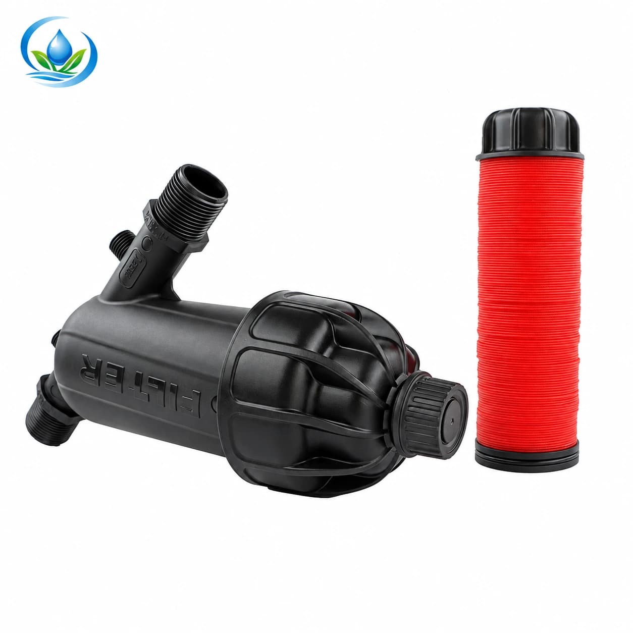
The Y-body disc-filter family is a separate product comparison for final particle protection. For example, F63YD is listed with a 2-inch connection, 120-mesh grade, maximum flow of 25 m³/h and maximum pressure of 8 bar. The two maxima are separate limits and do not establish a preferred operating point. Its matching nominal connection size does not prove that F63YD and F63LX form an approved pair. Confirm the emitter requirement, actual duty, connection standard and pressure budget for each component.
Do not buy a finer element merely because a separator discharged sand. Its material, quantity and behavior need to be understood in the context of the existing filtration sequence. Equally, a successful collector purge does not make the final filter unnecessary. The filtration selection guide explains the different jobs of the stages. Order a final-filter option only when its documented grade and operation match the protected devices and the material reaching it.
Keep the two service records distinct after any replacement: separator collection and discharge on one line, downstream element inspection on another. Use model-specific service decisions for both. Include the names of permitted crop groups and the observation points in the record, so a later change in zone flow is visible during troubleshooting. This also helps a buyer reorder the correct element or valve without treating every dirty-water symptom as a reason to replace the entire headworks.
Finish with a small, justified parts decision
The useful outcome may be no purchase, a confirmed service part for the existing model, a corrected approved discharge route or a fully specified replacement separator. State which observation supports that outcome and what remains unresolved. Include the installed model, flow case, collector service history, final-filter condition and photographs of the mating connections in the support request. The headworks access guide helps check that the resulting arrangement can still be maintained at the site.
Before placing an order, confirm the selected item's current sale unit, availability, included parts and delivery information. Keep any model-specific operating document with the installation record. An irrigation water filter purchase becomes more precise when the buyer can distinguish retained sediment, an obstructed discharge route, an unsuitable operating flow and a damaged final element. That distinction directs spending toward the identified problem while preserving the protection the crop outlets still require.
Before you order
Compare this guide with the specifications for your exact product, selected option, water supply and field conditions. Your equipment requirements take priority over a general example.
Compare irrigation products