
How to Install a Drip Irrigation System for a Vegetable Block: From Water Source to First Flush
Install and commission one vegetable drip zone in a practical sequence, from measured water source and accessible filter to row takeoffs, first flush and acceptance checks.
Published by IrriNex Store
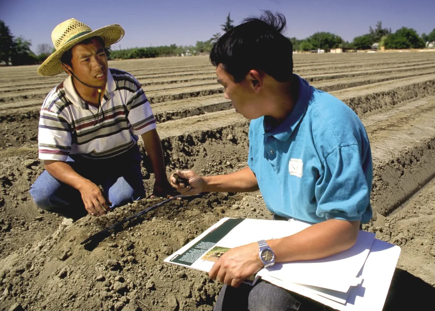
Learning how to install a drip irrigation system for a vegetable block means following the water from its source to a tested row, then proving the first zone works before copying it. The installation is more than laying tape. A clean route needs a protected supply, a serviceable filter, suitable pressure control, a supported delivery pipe, correctly matched row starts, accessible ends and a deliberate first flush. This guide walks through a new surface-laid vegetable block in the order a crew can check it. It assumes the hydraulic design and the selected product limits have already been confirmed; it does not turn an unmeasured pump or a product-family photograph into an installation specification.
Freeze the first zone layout before cutting pipe
Mark one representative block on the ground: source and isolation point, filter station, mainline route, header position, first and last rows, high and low spots, machinery crossings and a safe discharge area. Give the valve and each row a durable name. Count the rows that will run together and record their actual lengths. Then compare this field marking with the approved zone drawing. A field obstacle can move a header several metres; that change may alter the pipe length, number of bends and pressure available at the final row. Correct the drawing before cutting material.
Lay out the chosen pipe and fittings beside the route without opening every package. Match the printed option code to the order, not just the diameter shown on a carton. If a part is missing, do not replace it with a similar black connector of unknown thread or retention style. Make a simple connection schedule: supply outlet to filter, filter to mainline, mainline to zone header, header to each takeoff, takeoff to lateral and lateral to its end closure. The earlier component shopping list helps identify omitted groups; this guide starts after the groups have been chosen and asks whether every physical transition can actually be assembled.
Keep the first block accessible while testing. Leave room around the filter bowl and gauges, keep valves reachable from a walking route, and choose row ends that can be opened without sending discharge through a harvest path. If the proposed layout crosses traffic, fragile beds or buried utilities, revise the route under the farm's work procedure. Do not hide an untested header beneath mulch or soil just to finish the field quickly.
Prepare the source and headworks for a controlled start
Identify the actual water source and the authority for turning it on. Inspect the intake, pump or tank outlet, shutoff, visible leaks, strainers and any required source protection. If a new source connection is needed, confirm its pressure, thread or flange and installation method from its documentation. A backflow device, where required, must be selected and installed to the applicable local rule; a check valve shown in a generic drawing is not proof of compliance. Keep fertilizer injection isolated during clean-water commissioning unless the installed system's procedure explicitly says otherwise.
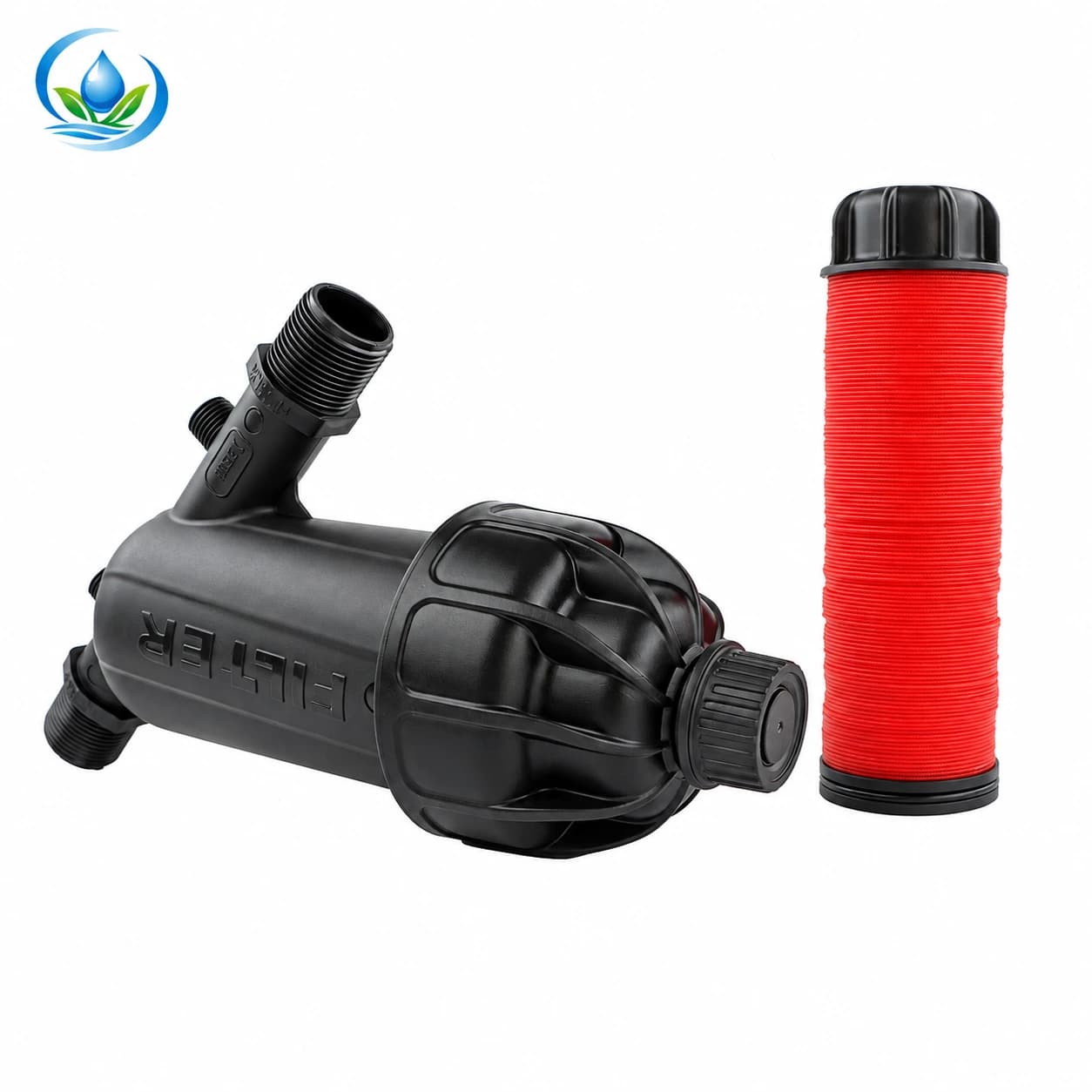
Fit the chosen filter where its element can be removed and its dirty side drained safely. The published Y-body disc filter has a 120-mesh family listing, but a mesh label alone does not establish that a particular size will pass this zone's flow or handle the source debris. Select the exact connection and flow option, check its pressure limit and compare the filtration grade with the tape maker's requirement. Note flow direction and sealing method on the actual housing. Leave enough space to see a pressure gauge before and after the station if the design uses that comparison.
Pressure must be checked while water moves, not only at a closed tap. The drip pressure guide explains the inlet and far-row measurement points. Before opening the new block, confirm that the specified regulator or pump control is present and that its flow and pressure range match the chosen tape. A regulator cannot raise weak source pressure. Keep its flow arrow, isolation valve and service instructions with the installation sheet so the crew does not diagnose low delivery by tightening unrelated fittings.
Lay and join the delivery route without hiding its weak points
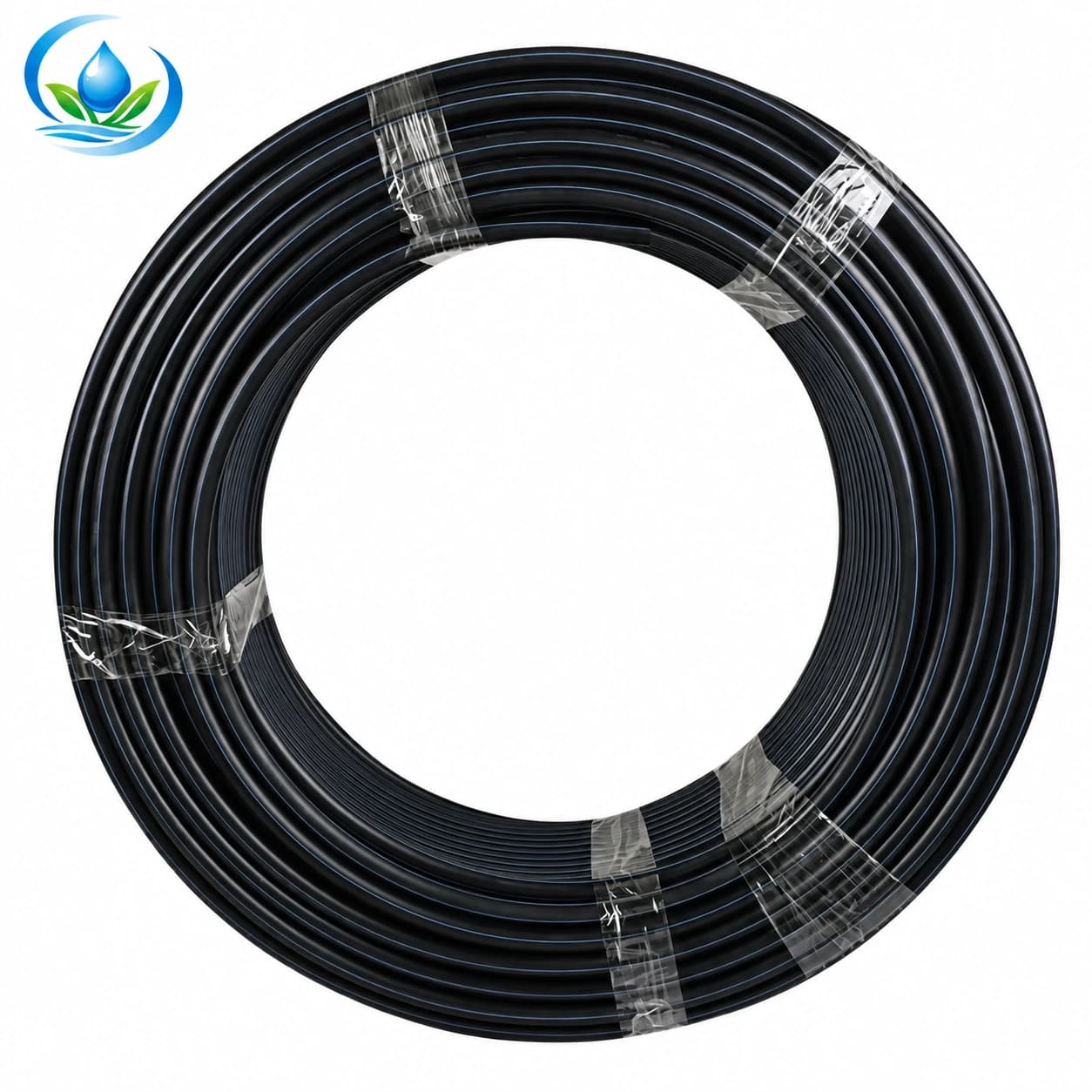
Place the mainline along the marked route and support or protect it as the selected pipe and farm conditions require. The PE irrigation mainline family lists several outside diameters and pressure classes; the exact selected option determines which couplers, tees, elbows and restraints belong here. A 32 mm marking on two products does not tell you their wall series, mating geometry or safe joining procedure. For buried work, follow the design, utility-locating, trench and bedding requirements; for surface work, protect exposed pipe from vehicles, sharp edges and movement when it fills.
Assemble from the source toward the header, leaving planned flushing outlets accessible. Keep pipe openings covered between operations so soil from the trench or bed cannot enter. Cut squarely with a suitable tool, remove loose fragments and use the approved joining method for that pipe and fitting. Do not force an adapter to seal by adding tape or clamps when the thread standard, gasket or pipe dimension is wrong. Support heavy valves and filters separately rather than letting their weight hang from a flexible joint.
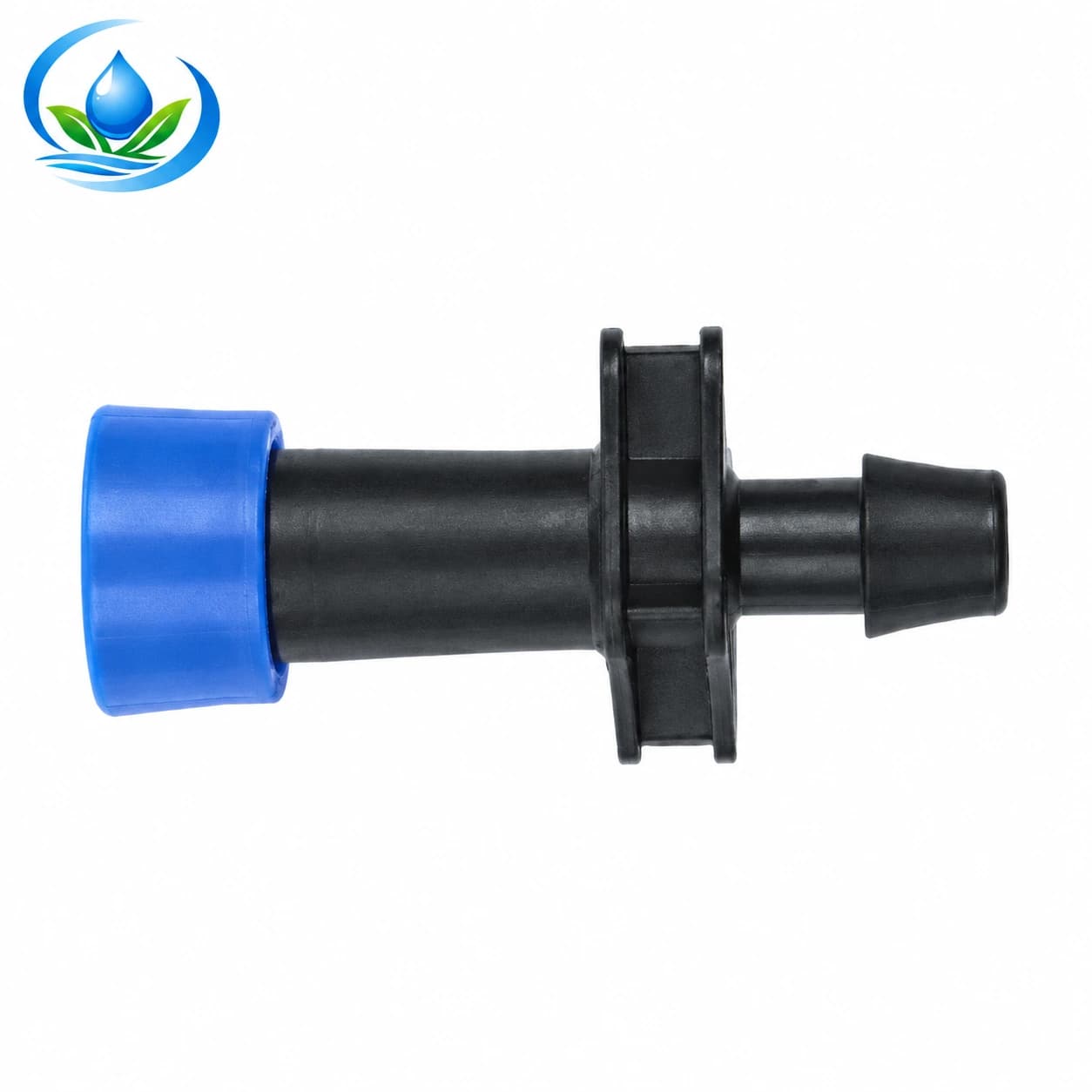
Before drilling a row of takeoff holes, verify the header's actual outside diameter, wall and the approved hole or sealing method. Place one trial connection at an accessible location. The lock-ring start offtake is a published nominal 16 mm connection family, but its name does not establish a fit with every thin-wall tape, header hole or gasket. Confirm the selected start, receiving pipe and lateral as one assembly. The fittings guide helps separate barbed, locking and threaded interfaces. A leak at the first test joint is cheaper to investigate than the same leak repeated across the block.
Set one surface tape row, then copy the handling method
Choose a straight row that represents the bed width, soil preparation and approach to the header. Keep the roll protected until it is ready to feed. Check the exact flat-emitter drip tape option for diameter, wall, outlet spacing and roll length. The Store family offers different combinations; its family page does not supply a verified emitter flow for every option. Record the delivered code and obtain the specific flow and operating-pressure directions before calculating the final zone demand or setting a regulator.
Set a suitable reel so the tape pays out without scraping, stretching or twisting. Confirm the actual factory outlet side from the roll's instructions, then keep it facing as directed while laying the first row. The emitter-side installation guide covers identification and twist control in detail. Here the acceptance question is broader: does this particular row connect to the header without rotating at the start, follow the planted bed without a damaging kink, reach a serviceable end and remain clear of machinery? Check along the whole row, not only the first metre.
Cut and attach the first lateral only by the selected tape and fitting instructions. Leave the end open or fit its planned flush outlet for commissioning. If the first connection needs excessive force, leaks dry, grips only the outside edge or twists the tape when tightened, stop and check the mating profile and wall range. Do not assume another nominal 16 mm part will solve the problem. After one correct trial, label the start and end parts and repeat the measured layout on the remaining rows. Keep the ends visible until the first run is accepted; covering an untested end makes later repair harder.
Flush in water-flow order before closing the laterals
New installation can leave cuttings, soil or packaging fragments in a pipe even when the incoming water is filtered. Arrange a controlled discharge route and check that opening an outlet will not undermine a bed, contaminate a waterway or endanger a worker. Follow the chosen system's valve, pump and filter instructions. In general, work downstream: clear the main delivery path through its planned outlet, then the header or submain, then appropriate groups of laterals. Do not send mainline debris into newly connected emitters. The exact number of laterals opened together and the flush flow or duration depend on the installed hydraulic design; a universal “open every end” rule can leave too little velocity in each row.
Have one person control the source while another observes a secured outlet where the farm procedure allows it. Before changing a cap or fitting, isolate the affected supply and release pressure. Start and stop through the documented valve sequence, avoiding abrupt changes that could move a pipe or open a weak joint. Watch the beginning and later part of each discharge; note solids, colour and whether the outlet changes. Clear-looking water at one end shows only what left that end at that moment. It does not prove every emitter is unobstructed.
The lateral flushing guide gives the detailed in-season end-access and record method. For a first installation, record which mainline, header and row groups were opened before any end is closed. If a joint must be repaired during the flush, keep that section marked, repair with the water isolated and repeat the affected flush according to the equipment procedure. Once the prescribed sequence is complete, isolate and depressurize, fit the verified closures and count every end back into service.
Pressurize one zone and record its acceptance readings
Bring the closed first zone up under its specified starting procedure, allowing air to leave through the intended points. Watch the filter body, transitions, header takeoffs and ends for leakage or movement. Record operating pressure at the headworks and representative near and far row positions while the planned number of rows runs. If a flow meter is available, record the same operating case and a clean-filter reference. A pressure value without the valve configuration and flow state is difficult to compare later.
Inspect several outlets at the beginning, middle and end of representative rows. Use equal collection times if comparing delivered volumes. Look for a continuous row that is dry, a single damaged tape section, an inverted or twisted reach and wet soil that begins before the factory outlet. Distinguish a leaking joint from an emitter pattern. A visually wet first bed is not proof that the far bed receives the required water. Oregon State University Extension's irrigation inspection guide includes a microirrigation checklist; use its inspection mindset while applying the selected equipment's own operating limits.
Keep an acceptance sheet with date, source condition, valve names, selected tape and fitting codes, filter state, head and far-row pressure, representative collection observations, leaks, repairs and the person who checked them. Mark any measurement beyond the approved design range as unresolved. If the first zone is accepted, this record becomes a repeatable pattern for the next block and a baseline for future filter cleaning and troubleshooting.
Resolve a failed first run before repeating the installation
If no row receives water, start at the source and work downstream: confirm the correct valve is open, the pump or supply is operating, the filter path is clear and the zone connection is complete. If near rows work but far rows do not, compare pressure before and after the filter, at the header and at the far lateral. A loaded filter, wrong valve state, undersized delivery route, kink or excessive simultaneous demand produces different readings. Do not cure an unknown low-pressure problem by opening more rows or installing a larger-looking regulator.
If one start leaks, isolate and release pressure before touching it. Check the actual hole, seal, header wall, insertion depth and lateral side of that connection. A damaged single hole may require an approved repair and a new takeoff location; copying the same punch setting across all rows would multiply the defect. If one tape length leaks along its wall, identify whether it was abraded, kinked, punctured or damaged at a fitting. Use the leak-location guide before ordering replacement parts.
If the filter clogs quickly during the first run, examine the actual source water and upstream treatment rather than repeatedly cleaning the disc stack without explanation. If several outlets are weak after a clean flush, compare the selected tape's verified discharge and pressure requirements with the measured operating case. A wrong emitter-flow assumption can make the planned row count too high. Stop the expansion until the cause is corrected and the representative zone passes again. Replace a cracked component with the same confirmed specification only when its original selection remains suitable; change the design or interface when the fault is systemic.
Hand over a serviceable block and a precise next order
Before the crew moves to the next block, walk the tested route once more. Confirm each filter drain, valve, takeoff and row end is accessible and identified. Protect exposed pipe where vehicles or harvest operations could strike it. Save the as-built drawing, part codes, accepted pressure and flow observations and any open defects. A later operator should be able to isolate one zone, find its flush outlet and replace one damaged connection without reconstructing the installation from memory.
Count the remaining parts from the accepted first zone rather than from an early estimate. The order should name the exact pipe option, tape option, filter size, start assembly, approved end closure, number of rows and realistic service spares. Check current package quantities and availability on each option page. Keep any uncertain mating dimension as a named question with two product links and a photograph of the measured pipe; do not let it become an unverified substitution during installation. Once the first zone is proven, the same field sequence can be repeated and measured in the next block.
Before you order
Compare this guide with the specifications for your exact product, selected option, water supply and field conditions. Your equipment requirements take priority over a general example.
Compare irrigation products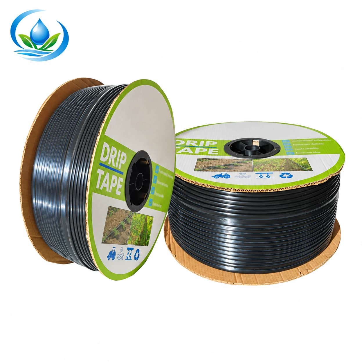
(NRCS_Photo_Gallery).jpg)
(NRCS_Photo_Gallery).jpg#Licensing)